en Installation and electrical connection
18 WILO SE 2017-03
6.5.2.2 Test the resistor of the temperature sensor
Measure the resistor of the temperature sensors with
an ohmmeter. The bimetallic strips must have a meas-
ured value of 0Ohm (passage).
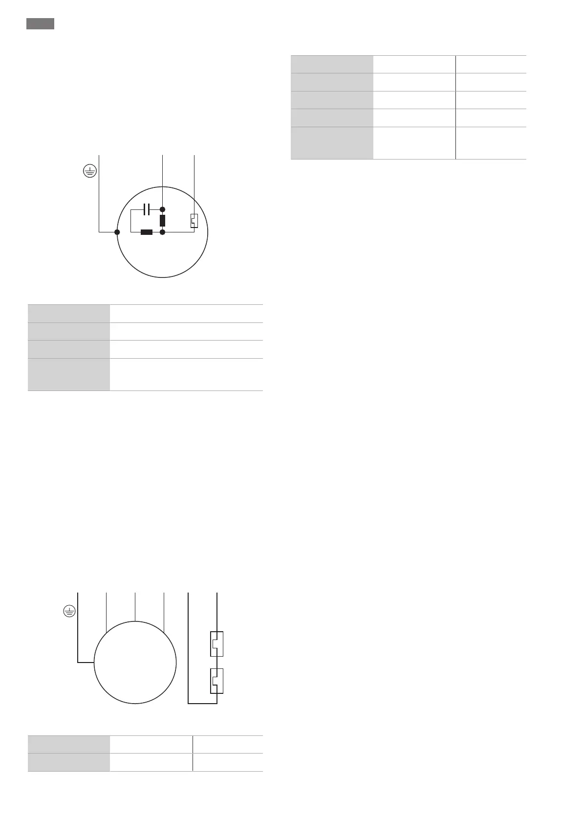
6.5.3 Connection of the single-phase motor
U1/Z1
bn
U2
bu
C
r
M 1~
gn-ye
LNPE
Fig.8: Connection diagram single-phase motor
Wire colour Terminal
Brown (bn) L
Blue (bu) N
Green/yellow (gn-
ye)
Earth
The single-phase current version is equipped with a
shockproof plug. The connection to the mains is estab-
lished by inserting the plug into a socket. The plug is
not overflow-proof. Install the socket so that it is
overflow-proof! Observe the information on the pro-
tection class (IP) of the plug.
DANGER!If the pump is connected directly to the
switchgear, dismantle the plug and arrange for the
electrical connection to be carried out by a qualified
electrician!
6.5.4 Connection three-phase motor
W
5
1
2
V
4
U
3
M 3~
gn-ye
L3L2 2120L1PE
250 V (AC); 2,5 A; cos φ = 1
Fig.9: Connection diagram three-phase motor
Wire number Designation Terminal
1 20 WSK
2 21 WSK
3 U L1
4 V L2
5 W L3
Green/yellow (gn-
ye)
Earth PE
For three-phase current motors, a clockwise rotating
field must be available. The three-phase version is
equipped with a CEE plug or with a free cable end:
▪If a CEE plug is supplied, connection to the mains is es-
tablished by inserting the plug into a socket. The plug is
not overflow-proof. Install the socket so that it is
overflow-proof! Observe the information on the pro-
tection class (IP) of the plug.
▪If there is a free cable-end, the pump must be connec-
ted directly to the switchgear. DANGER!If the pump is
connected directly to the switchgear, arrange for the
electrical connection to be carried out by a qualified
electrician!
6.5.5 Monitoring equipment connection
All monitoring equipment must be connected!
6.5.5.1 Monitoring of motor winding
Single-phase current motor
Thermal motor monitoring is self-switching for single-
phase current motors. The monitoring function is al-
ways active and does not need to be connected separ-
ately.
Three-phase current motor with bimetallic strip
Bimetallic strips are connected in the switchgear itself
or via an evaluation relay.
Connection values: max. 250V(AC), 2.5A, cos φ = 1
When the threshold is reached, deactivation must
take place.
In the version with an attached plug, the thermal motor
monitoring is pre-wired and set to the correct value in
the plug.
6.5.6 Motor protection adjustment
Motor protection must be set depending on the selec-
ted activation type.
6.5.6.1 Direct activation
At full load, set the motor protection switch to the
rated current (see rating plate). At partial load, it is re-
commended to set the motor protection switch 5%
above the current measured at the duty point.