WIL-IO-SP-WCC17001-11
5
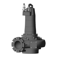
Picture 1
8. OPERATION
Do not handle this pump or plug in or unplug this pump with wet hands or while standing in water, unless
you are certain all power has been turned off to the pump. Remember, the pump should be connected only
to a properly grounded, GFCI outlet.
1. Make certain the pump is submerged in water. Running the pump dry can damage the shaft seal.
2. Insert the float switch piggy-back plug into a properly 115V GFCI grounded power outlet and the pump plug into
the piggyback plug. The pump will start operating when the float switch moves up over the pump top. The water
will be pumped out. When the water lowers to certain level, the float switch will turn off the pump.
3. The motor is equipped with an automatically resetting thermal overload protector. If the motor gets too hot, the
overload protector will shut off the pump before it is damaged. When the motor has cooled sufficiently, the
overload protector will reset, and the motor will restart.
NOTICE: If the overload protector stops the pump repeatedly, disconnect the power from the pump and check to
find the problem. Low voltage, a long extension cord, clogged impeller, or water that is too hot can cause motor
overheating.
9. MAINTENANCE
• Periodically unplug the pump, making certain your hands are dry, and you are not standing in water. When the
power is disconnected, inspect the pump inlets and remove all debris, then plug pump back into the grounded (GFCI)
outlet.
• To clear a pump clogged with debris, first, UNPLUG PUMP from electrical power. Then referring to Picture 2 below,
unscrew the stainless screws #1, then the volute #5, and the seal gasket #4. Use a flathead screwdriver to hold the
shaft #2 then turn the impeller #3 counter-clockwise to release the impeller. Remove debris from around the shaft
and on and under the impeller. Then reassemble the impeller, gasket, volute, See Picture 2.
Check valve
 Loading...