English
10 Wilo AG 05/2006
6 Description and operation
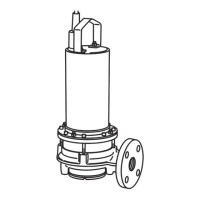
6.1 Pump description (Figure 1)
The submersible motor pump is driven by an
enclosed motor that is impermeable to presswa-
ter. Motor and pump have a continuous shaft. The
flow medium enters from below through the cen-
tral suction opening and exits by the vertical pres-
sure-pipe connection. The pump has a built-in
non return valve (pos. 5).
The TS 40 pumps are delivered with a half-open
impeller (pos. 23). It pumps solids up to 10 mm Ø
(no fibrous materials such as grass, leaves or rags).
For stationary installation, the pump is screwed to
a fixed pressure-pipe (R 1½), and for transporta-
ble installation to a hose connection.
The motor of both types is sealed with a mechan-
ical tandem seal (pos. 20) on the medium and
motor side against the pump housing. So that the
seals are lubricated and cooled in the case of dry
running, the chamber between the mechanical
seals is filled with oil.
CAUTION! Risk of leak!
If the mechanical seal is damaged, small quanti-
ties of oil may leak into the flow medium.
The motors are fitted with a thermal motor pro-
tection (1
~
: thermal winding contact (WSK), 3
~
:
thermal motor control) that automatically
switches the motor of if there is a threat of it over-
heating and switches it back on again once it has
cooled down. A capacitor is fitted at the 1
~
motor
to generate the rotary field.
7 Installation and electrical connection
Installation and electrical connection should be
carried out in accordance with local regulations
and only by qualified personnel!
WARNING! Risk of personal injury!
The relevant accident precaution regulations
must be observed.
WARNING! Risk of electric shock!
Potential dangers caused by electrical energy
must be excluded.
Local or general regulations [e.g. IEC, VDE, etc.]
and directives from local energy supply compa-
nies are to be followed.
7.1 Installation
The pump is designed for stationary and trans-
portable wet-well installation.
CAUTION! Risk of damage to the pump!
• Only suspend the pump using a chain or rope
from the transport loop, never by the electric
cable or pipe / hose connection.
• When the pump is lowered into the shaft or pit
the connecting cable must not be damaged.
• The pump must be installed in a frost-free place.
•
The shaft must be free from coarse solids (e.g.
building rubble) prior to installation and commis-
sioning.
• See catalogue for installation dimensions.
• The pressure-pipe must show the pump’s nominal
width (R 1½, possibility for expansion).
7.1.1 Stationary wet-well installation
In the case of stationary wet-well installation of
TS 40 pumps with pressure-pipe the pump is to be
positioned and secured such that:
• the pressure-pipe connections do not bear the
weight of the pump,
• the load of the pressure-pipe does not act on the
connecting sleeve.
7.1.2 Transportable wet-well installation
In transportable wet-well installations, the pump
in the shaft is to be protected against tipping over
and slipping. (e.g. secure the chain with slight pre-
stressing).
NOTE:
If used in pits without a solid floor, the pump must
be placed on a sufficiently large plate or be sus-
pended in a suitable position on a rope or chain.
7.2 Electrical connection
WARNING! Risk of electric shock!
Electrical connection must be carried out by an
electrical installer authorised by the local power
supply company in accordance with the applica-
ble local regulations (e.g. VDE regulations).
• Check that the mains current and voltage comply
with the data on the rating plate.
Pos. Part description Pos. Part description
1 Cable assy 14 Capacitor
2
Head Cover 15 Gasket, Head Cover
3
Adaptor cover 16 End bracket (B)
4 Motorhousing 17 Rotor assy
5
Non-return valve 18 Stator
6
Pipe connection 1 ½" 19 End bracket (A)
7 Delivery port, Flange 20 Mechanical seal
8
Gasket, Flange 21 Oil drain plug with seal
9 Cover, Casing 22 Washer
10
Pump casing 23 Impeller
11
Floatswitch 24 Gasket, Casing
12 Cable holder 25 Strainer
13
Sealing, cable entry 26 Hose nozzle R1½ (outside thread)
 Loading...