Installation and operating instructions Wilo-DrainLift Con 19
English
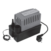
6.2 Function
The condensate lifting unit is controlled via three switching points.
• If the condensate level in the condensate collection reservoir reaches 43 mm
(Fig. 2, item B), the cut-in level is reached and the pumping sequence begins.
• If the condensate level in the condensate collection reservoir drops to 27 mm
(Fig. 2, item A), the cut-off level is reached and the pumping sequence stops.
• If the condensate level in the condensate collection reservoir reaches 67 mm
(Fig. 2, item C), the alarm level is reached and the alarm switch triggers the
alarm.
The alarm switch is built into the unit, and serves as an overflow protection
measure. It is connected to the unit in which the condensate collects or to the
Wilo-DrainAlarm 2 by the 1 m long alarm cable.
The unit is fitted with a monoblock centrifugal pump. The unit motor has a ther-
mal winding contact (WSK) which switches off at a temperature of 130 °C and
automatically switches on again once the temperature has cooled.
7 Installation and electrical connection
DANGER! Risk of fatal injury!
Incorrect installation and improper electrical connections can be life-threat-
ening.
• The installation and electrical connection must be carried out only by quali-
fied personnel in accordance with applicable regulations.
• Observe the regulations for accident prevention.
• Before installation and electrical connection, disconnect the system from
the power supply and make sure it cannot be switched on by unauthorised
persons.
• Disconnect the mains plug!
7.1 Preparations for installation
• Select an installation location suitable for the size of the unit and accessibility
of the connections.
• Dimensions of the unit (H x W x D): 210 mm x 120 mm x 167 mm
• The condensate lifting unit must be installed in a dry, well-ventilated, frost-free
room.
NOTE! The motor unit of the condensate lifting unit can be placed either clock-
wise or anti-clockwise on the condensate lifting unit, depending on the instal-
lation site.
• Press in the housing clips (Fig. 1, item 3).
• Remove the motor unit.
• If necessary, turn the motor unit, set it in place and press down until the housing
clips click audibly.
 Loading...