English
Installation and operating instructions Wilo VR System 17
1 General
Installation and commissioning by qualified per-
sonnel only!
1.1 Intended use
The VR control device is for automatically control-
ling pressure boosting systems consisting of 1 to
4 pumps with integrated frequency converters of
the WILO- MVIE, MVISE, MHIE and HELIX VE series
or external frequency converters. These operating
instructions only apply to operation with WILO
pumps with integrated frequency converters.
If external frequency converters are used, the cor-
responding installation and operating instructions
are to be taken into account.
Water supply and pressure boosting in residential,
commercial and public buildings, hotels, hospitals,
department stores and for industrial systems are
the fields of application.
When used in conjunction with suitable signal trans-
mitters, the pumps offer low-noise and energy-
saving operation. The performance of the pumps
is adapted to the constantly changing require-
ments in the pressure boosting system.
1.2 Product information
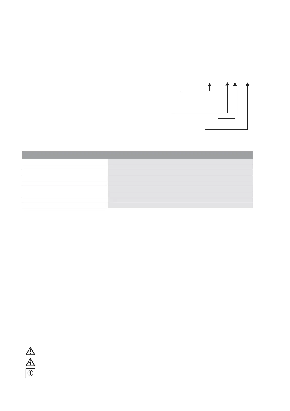
1.2.1 Type key
VR-Control 4 x 1.1KW WA
Device desi
gnation
1 fo
r 1 pump
2 fo
r 2 pumps
3 for 3 pumps
4 fo
r 4 pumps
Power P
2
of the pumps that can be used
(see catalogue/data sheet for selection)
WA = Wall-mounted insta
llation
1.2.2 Connection and technical data
Operating voltages:
1~230 V (L1, N, PE)
3~400 V (L1, L2, L3, PE)
Frequency:
50/60 Hz
Protection class:
IP 54
Degree of contamination
3
Maximum ambient temperature:
40 °C
Pressure sensor:
P: 0 – 6 bar, 0 – 10 bar, 0 – 16 bar, 0 –25 bar
I: 4 – 20 mA
Mains-side fuse protection:
according to wiring diagram included
Further electrical technical data can be found on
the technical data sheet or rating plate.
Please state all the information on the system rat-
ing plate when ordering spare parts.
2Safety
These operating instructions contain basic infor-
mation which must be adhered to during installa-
tion, operation and maintenance. For this reason,
these operating instructions must, without fail, be
read by the service technician and the responsible
specialist/operator before installation and com-
missioning.
It is not only the general safety instructions listed
under the main point “safety” that must be adhered
to but also the special safety instructions with dan-
ger symbols included under the following main
points.
2.1 Indication of instructions in the operating
instructions
Symbols:
General danger symbol
Danger due to electrical voltage
NOTE!
Signal words:
DANGER!
Acutely dangerous situation.
Non-observance results in death or the most
serious of injuries.
WARNING!
The user can suffer (serious) injuries. 'Warning'
implies that (serious) injury to persons is proba-
ble if this note is disregarded.
CAUTION!
There is a risk of damaging the product/unit.
'Caution' concerns possible damage to the prod-
uct that could occur if this note is disregarded.
NOTE:
Useful information on handling the product. It draws
attention to possible problems.
Information that appears directly on the product,
such as
• Direction of rotation arrow
• Identification for connections
• Rating plate
• Warning sticker
must be strictly complied with and kept in legible
condition.