English
24 WILO SE 07/2011
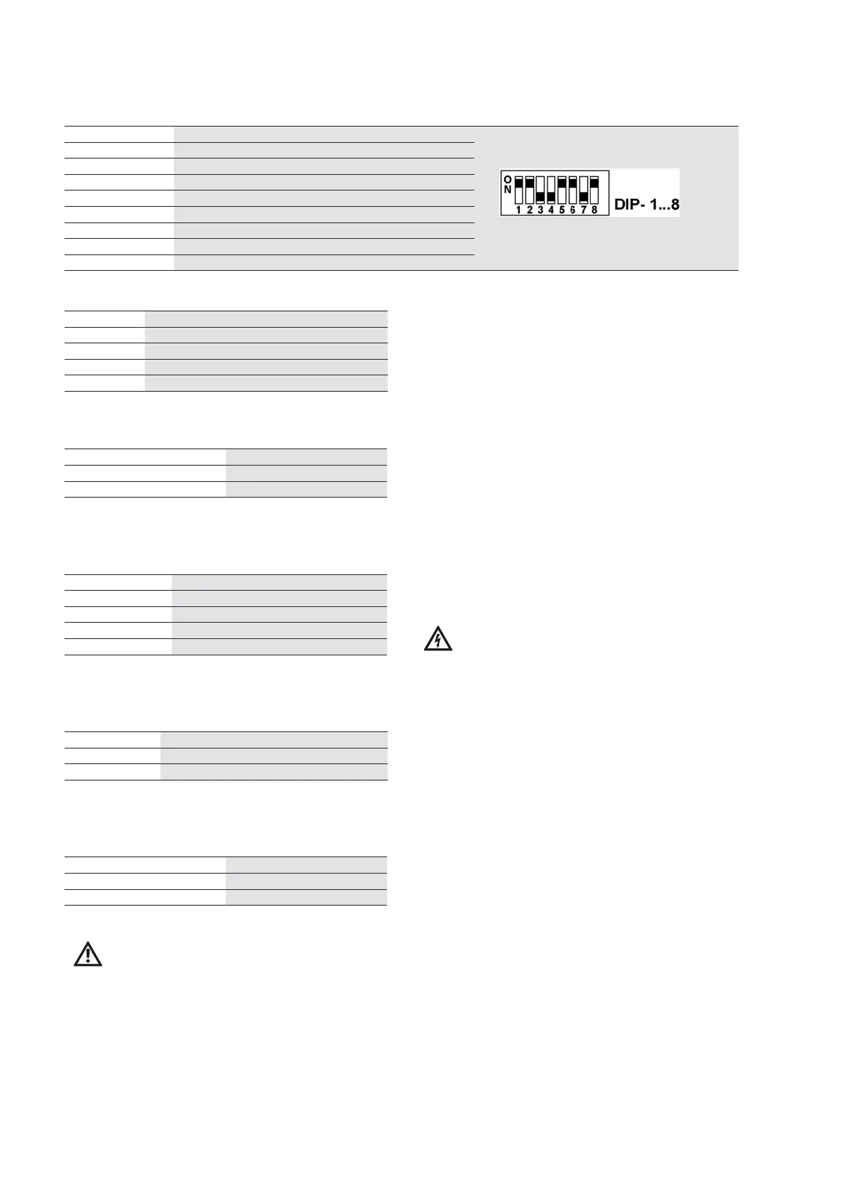
4.2.3 DIP switch setting
• Overview (Fig. 4, DIP switch)
DIP switch Function
1 Number of pumps (bit 0)
2
Number of pumps (bit 1)
3
Number of pumps (bit 2)
4
Standby pump
5
Pressure sensor type (bit 0)
6
Pressure sensor type (bit 1)
7
SSM inverted
8
Lock parameter
• Setting the number of pumps
Quantity
DIP – 1 DIP – 2 DIP – 3
1
ON OFF OFF
2
OFF ON OFF
3
ON ON OFF
4
OFF OFF ON
Factory setting: according to system type
• Standby pump
Standby
DIP – 4
yes
ON
no
OFF
Factory setting: according to system type
• Pressure sensor type: (measurement range)
Sensor
DIP – 5 DIP – 6
6 bar
OFF OFF
10 bar
ON OFF
16 bar
OFF ON
25 bar
ON ON
Factory setting: according to system type
• Logic reversal of collective fault signal
Reversal
DIP – 7 Relay active
yes
ON No fault
no
OFF Fault
Factory setting: DIP – 7: OFF, no logic reversal
• Setting the locking of parameter changes
Locking
DIP – 8
yes
ON
no
OFF
Factory setting: DIP – 8: ON, lock
CAUTION! Risk of malfunctions!
Before making adjustments to the DIP switches,
switch off the device! The modified settings are
only applied when the power supply is restored.
4.3 Scope of delivery
• Wilo VR-Control control device
• Installation and operating instructions
•Wiring diagram
• Double bit switch cabinet key
5Installation
5.1 Installation
The VR/Control control device is delivered as a com-
pletely assembled unit. The wall-mounted instal-
lation of the devices is performed using 4 screws
8 mm, e.g. on a base frame or the wall. Install the
control device in a dry, vibration- (acceleration < 2g
in all directions) and frost-free place that is pro-
tected from direct sunlight.
Devices for higher capacities are delivered as floor
models.
5.2 Electrical connection
DANGER! Risk of fatal injury!
The electrical connection must be made accord-
ing to the local regulations (VDE regulations) by
an electrical installation engineer approved by
local energy supply companies.
• The type of current, system type and voltage of
the mains connection must correspond to the
specifications on the rating plate
• Observe the rating plate data of the pump
motors to be controlled
• Observe the fuse protection on the mains side
according to the system's rating plate
• If residual-current-operated protection
switches are used, the corresponding regula-
tions and the operating instructions for the
pump(s) to be connected are to be observed.
• Wiring is to be performed in accordance with the
wiring diagram enclosed
• Earth the pump/installation in accordance with
the regulations
• The connection lines are to be installed in such a
way that there is no contact with the pipes and
the pump and motor housings under any circum-
stances. At ambient temperatures > 30 °C, please
take the corresponding redu
ction factors into
account!