For Technical Support, call 866-294-1660 or 435-673-5021.
13
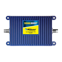
Amplifi er Specifi cations
Dual-Band Wireless
800/1900 MHz Specifi cations
Model Number 271247-50 271247-75
Outside antenna connectors F Female F Female
Outside antenna impedance 75 ohms 75 ohms
Inside antenna connectors TNC Female F Female
Inside antenna impedance 50 ohms 75 ohms
Dimensions 6.2 x 4.2 x 1.5 inch (15.7 x 10.7 x 3.8 cm)
Weight 0.64 lbs (0.29 kg)
Frequency 824-894 MHz / 1850-1990 MHz
1
Passband Gain (nominal)
800 MHz 60 dB Typical, 65 dB Maximum
1900 MHz 60 dB Typical, 65 dB Maximum
2
20 dB Bandwidth (nominal) Uplink Downlink
800 MHz 44 MHz 48 MHz
1900 MHz 95 MHz 91 MHz
Power output 800 MHz 1900 MHz
Power output for single cell phone (uplink) 33.2 dBm 34.0 dBm
Power output for single received channel (downlink) 15.7 dBm 10.7 dBm
4
Power output for multiple transmitted channels (uplink) Maximum Power
The maximum power is reduced
by the number of channels:
Number of channels 800 MHz 1900 MHz
2 23 dBm 21.3 dBm
3 19.5 dBm 17.8 dBm
4 17.0 dBm 15.3 dBm
5 15.1 dBm 13.3 dBm
6 13.5 dBm 11.8 dBm
4
Power output for multiple received channels (downlink) Maximum Power
The maximum power is reduced
by the number of channels:
Number of channels 800 MHz 1900 MHz
2 6.2 dBm 5.2 dBm
3 2.7 dBm 1.6 dBm
4 0.2 dBm -0.9 dBm
5 -1.7 dBm -2.8 dBm
6 -3.3 dBm -4.4 dBm
Noise Figure (typical) 3.5 dB nominal
Isolation (uplink/downlink) > 90 dB
Power Requirements 110-240 V AC, 50-60 Hz, 8 W
Notes:
1. Nominal gain is the maximum gain at any frequency in the passband.
2. Nominal bandwidth is the difference between two frequencies that are adjacent to the passband where the amplifi cation is 20 dB lower than the passband
amplifi cation. One of the frequencies is lower than the passband and the other is higher.
3. The Manufacturer’s rated output power of this equipment is for single carrier operation. For situations when multiple carrier signals are present, the rating
would have to be reduced by 3.5 dB, especially where the output signal is re-radiated and can cause interference to adjacent band users. This power reduction is to
be by means of input power or gain reduction and not by an attenuator at the output of the device.
4. The maximum power for 2 or more simultaneous signals will be reduced by 6 dB every time the number of signals is doubled.
For Technical Support, call 866-294-1660 or 435-673-5021.
2
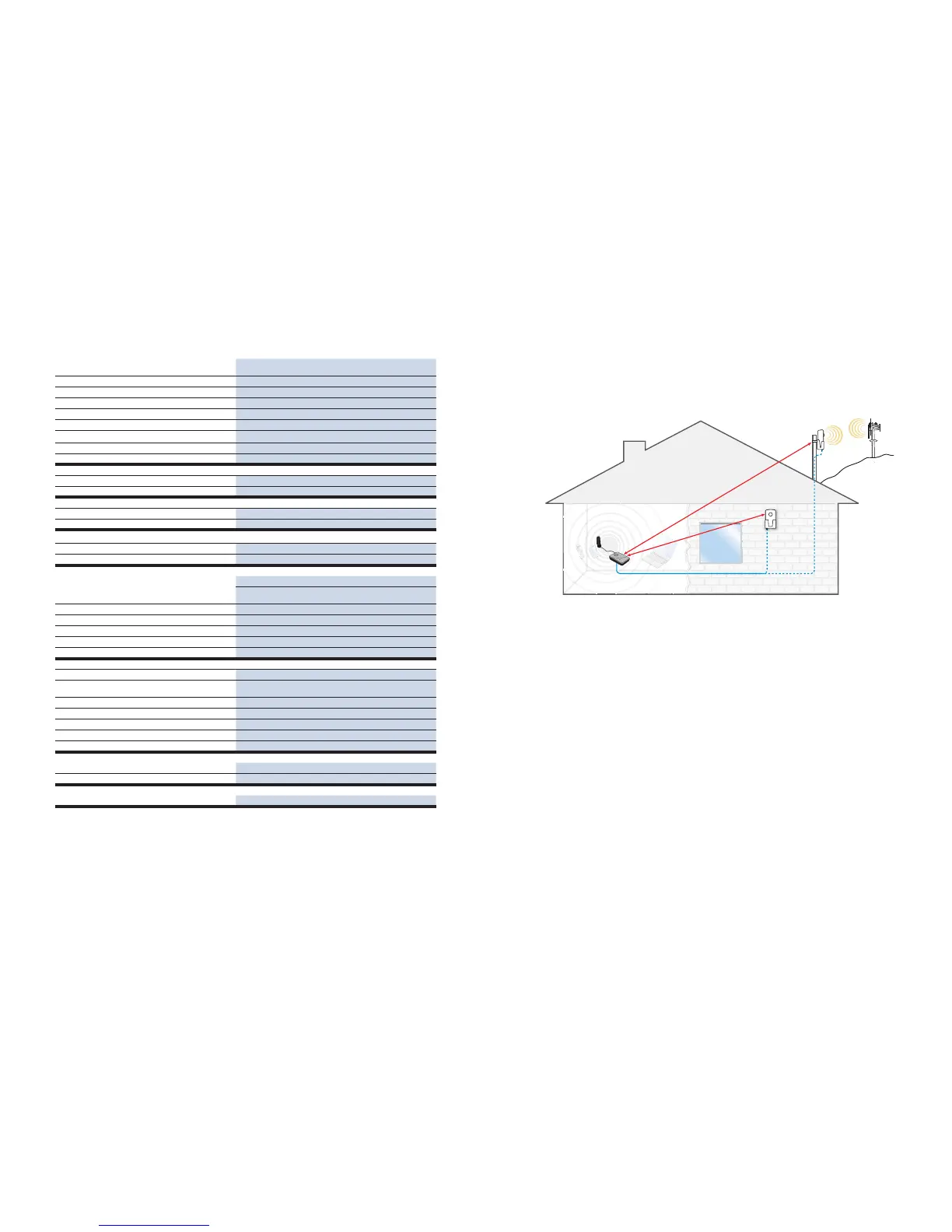
How it Works
Your Wilson SignalBoost DT Amplifi er works by picking up a stronger signal from an antenna mounted on a
pole or wall outside your building facing the cell site. The amplifi er then increases the signal and transmits it to
the desktop antenna. The desktop antenna then transmits the boosted signal to your cell phone or laptop data
card.
Reasons for Weak Cellular Signals
Anyone who uses a cell phone or cellular data card knows the frustration of not being able to connect to or
maintain a strong cellular signal. When this occurs, it’s generally due to one of two reasons:
1. Location of the Nearest Cell Tower – Cell towers are situated to provide broad coverage; however, there
are many areas in which signal strength may be reduced by topographic features or by local government
restrictions on the height or placement of the towers themselves. Rural areas generally have fewer cell
towers than urban regions.
2. Natural and Man-made Obstructions – Signal strength can also be negatively affected by trees, hills,
buildings and other obstructions. You may be relatively close to a cell tower but still unable to make a call.
This often occurs in homes, offi ces and other buildings in which stucco, concrete or metal walls block the
signal.
The SignalBoost DT works with two antennas (included). The desktop antenna communicates with your cell
phone or laptop data card, and the cradle antenna communicates with the cell tower. The cradle antenna is
designed for installation outside on a wall or a pole. (see Figure 1).
The cradle antenna receives the outside signal and sends it through the coax cable to the SignalBoost DT,
where it is amplifi ed and retransmitted much more strongly through the desktop antenna into the room. When
the desktop antenna picks up a signal from your cell phone or data card, the amplifi er boosts that signal and
transmits it through the cable to the cradle antenna and back to the cell site. (Note: the SignalBoost DT will
only operate if there is adequate signal to amplify.)
Cradle Antenna
Option B (outdoor)
Wall Mount
Cradle Antenna
Option A (outdoor)
Pole Mount
SignalBoost DT
Area Needing
Increased
Signal
Cell
Tower
Desktop
Antenna
Aim toward
cell tower
Aim toward
cell tower
Minimum 20 feet of separation
Minimum 20 feet of separation
Note: If 20’
separation is not
possible, see page 5.
Figure 1