Do you have a question about the Wilson Electronics 271245 and is the answer not in the manual?
Wilson Electronics products are protected by Wilson's 30-day money-back guarantee for acceptable performance.
Wilson Electronics amplifiers are warranted for one year against defects in workmanship and materials.
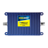
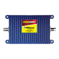
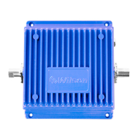
Details the Mobile Wireless Dual-Band Amplifier, its components, and its function to improve cell signal.
Highlights various Wilson antennas available for customizing the amplifier installation.
Guide to properly installing the dual-band wireless amplifier, emphasizing reading all steps before starting.
Illustrates typical installation setups for inside antenna and universal connector configurations.
Select a location in the center of the vehicle's roof, 12 inches from other antennas and free of obstructions.
Instructions on running the antenna cable through the door seal for a professional installation.
Choose a location away from heat, sunlight, moisture, with proper ventilation, e.g., under seat, trunk, or dash.
Connects the outside antenna cable to the amplifier and details the two options for inside signal delivery.
Install the low-profile antenna 8-12 inches from where the phone/data card is used, avoiding metal within 4 inches.
Place the inside antenna on the side of the driver's seat, angled like the phone, for maximum signal strength.
Connect the universal connector directly to the cell phone or data card using provided Velcro, allowing 24 hours for adhesive curing.
Guidance on adjusting the connector for best signal by testing in a weak signal area.
Connect the DC power supply to the amplifier and insert into the vehicle's power socket. Use only the provided supply.
Options for powering the amplifier via ignition switch to avoid battery discharge, and notes on amplifier casing temperature.
Do not plug amplifier directly into phone with adapter; do not plug DC power supply until cables are attached.
Ensures proper separation distances for inside/outside antennas and warns against illegal antenna gain.
Explains green PWR light for power up and green 800/1900 MHz lights indicating amplification of outside signal.
Details red lights for oscillation and amber lights for overload, with corrective actions.
Lists model number, connectors, impedance, dimensions, weight, and frequency range of the amplifier.
Details passband gain, bandwidth, power output for single/multiple cell phones, and noise figure.
| Frequency Band | Dual Band |
|---|---|
| Max Gain | 65 dB |
| Gain | 65 dB |
| Maximum Gain | 65 dB |
| Noise Figure | 5 dB |
| Impedance | 50 Ohms |
| Uplink Frequency Range | 824-849 MHz, 1850-1915 MHz |
| Downlink Frequency Range | 869-894 MHz, 1930-1995 MHz |
| VSWR | 2.0:1 |
| Operating Temperature | +50°C |
| Frequency Range | 824-894 MHz, 1850-1995 MHz |