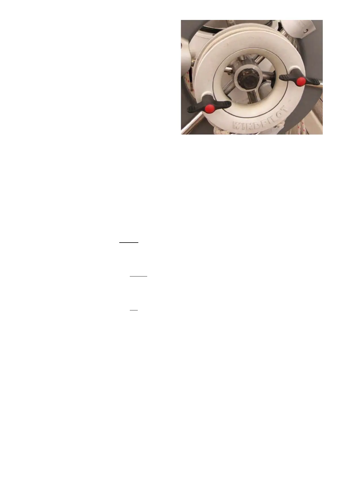
you tension the cord, the more the block pulls the
slack out of the steering lines.
• Releasingthisblockprovidessufficientslackto
uncouple the snap shackles at the connection
point.
• Theblockcanthenbeusedtore-tensionthe
steering lines once the snap shackles have been
reconnected prior to switching over to WINDPILOT
steering.
1.6.8.5 TRANSMISSION RATIO
• Thewheeladaptorisdesignedformechanical
wheel steering systems with a range of around two
and a half revolutions from stop to stop and a wheel
diameter of approximately 60 cm/24 in. This means
in practical terms that the maximum line travel of 25
cm/10 in is sufficient to turn the wheel through half
a revolution given, perfect transmission.
1.6.8.6 VARIABLE FORCE TRANSMISSION
• Theforcetransmissioncharacteristicscanbe
adjusted using the slot in the pendulum arm 300
(see 2.2.6.2 Determining the Ideal Settings).
1.6.8.7 FORCE TRANSMISSION WITH WHEEL
STEERING: EXAMPLES
Example 1:
• Wheeldiameter=approx.60cm/24in
• Revolutionsfromstoptostop=2.5
• Positionofring315=approx.centred in the slot
Example 2:
• Wheeldiameter=approx.100cm/40in
• Revolutionsfromstoptostop=1.5
• Positionofring315=towardsthebottom of the slot
Example 3:
• Wheeldiameter=approx.55cm/22in
• Revolutionsfromstoptostop=3-4
• Positionofring315=towardsthetop of the slot
TEST
• Itisactuallyquitestraightforwardtoworkout
the key parameters for your boat - see 2.2.6.2
Determining the Ideal Settings.
1.6.9 STEERING LINES AND THE EMERGENCY TILLER
1.6.9.1 MECHANICAL WHEEL STEERING
• Connectingthesteeringlinestotheemergency
tiller of a mechanical wheel steering system will not
yield good steering because the tiller has to move
the whole of the steering mechanism from the
wrong end every time it tries to turn the rudder. It’s
like trying to turn the steering wheel of your car by
sitting in the road and tugging on the front wheels!
• Goodsteeringcanonlybehadbythisrouteifthe
transmission components of the wheel steering
system are completely disconnected from the
quadrant (emergency).
 Loading...