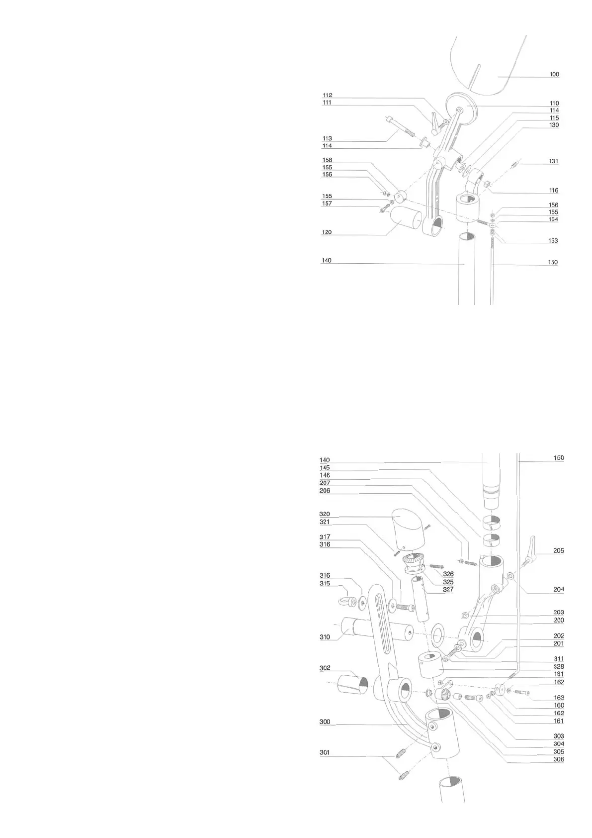
5.3.2 AT THE WINDVANE SHAFT
• Ifthewindvaneshaftwillnotturneasily(forcourse
adjustment) even when adjustment lever 205 is
released, remove locking screw 206/207 and raise
the windvane shaft.
• ApplyWD-40orTeflonsprayandreassemble,
taking care to ensure that bearing 141/142 is
properly positioned.
• Tightenlockingscrew206/207untilitstopsand
then loosen it slightly so that the windvane shaft
can turn freely. Screw 207 serves merely to hold
the shaft in place if the unit is lifted; it should not be
pressed hard against shaft 140.
5.3.3 AT THE RUDDER AXLE
• Ifthereisfrictionattherudderaxle,thesystemwill
have to be disassembled and cleaned.
5.3.3.1 DISASSEMBLY PROCEDURE
• Removethesystemfromthetransom.
• Removeredcap320.
• Removescrew327.
• Pushshaft255downoutofbevelgear325.
• Marktherelativepositionsofthetwogearsinthe
bevel gear linkage.
• Cleanbearing328.
5.3.3.2 ASSEMBLY PROCEDURE
• Checkthepositionofthetwogears.Theleveron
thesmallgear305shouldbeinthe‘quarterpast
twelve’ position.
• Checkthatthependulumarmisvertical.
• Check that the pendulum rudder blade is in line
with the keel.
• Checkthattheholeinbevelgear325isflushwith
the hole in shaft axle 327.
5.3.4 AT THE STEERING LINES
• Dotheblocksmovefreely?
• Arethetransmissionpathstoolong?
• Isthewheeltoofarfromthetransom(centre
cockpit)?
• Arethemainrudderbearingsstiff?
• Isthewheelsteeringsystemstiff?
5.4 THE PUSH ROD IS BENT
• Checkthebalanceproportionofpendulumrudder
blade 440 (see 1.7 The Pendulum Rudder).
• Thepushrodcanbestraightenedeasily.
5.5 THE WINDVANE SHAFT IS LOOSE
• Tightenbolts205
 Loading...