Do you have a question about the Wireless-tag WT32-SC01 and is the answer not in the manual?
Details the physical dimensions and mounting hole specifications of the WT32-SC01 development board.
Describes the ESP32-WROVER-B module, its Wi-Fi/BT capabilities, and memory configuration (Flash/PSRAM).
Specifies the capacitive touchpad interface, including I2C, pin count, and spacing.
Details the 3.5-inch LCM display, its SPI interface, resolution, and screen model.
Explains the board's 3.3V power supply and its isolation for system stability.
Defines the external power input, specifying voltage range (5-9V) and current recommendations.
Describes the function of the RST key, used to reset the ESP32 EN pin.
Details the USB Type-C interface for power, UART communication, and firmware downloads.
Covers the 2x20Pin expansion interfaces for adding functionality.
Explains the red LED power indicator that lights up when the USB cable is connected.
Describes the TXD and RXD indicators that flash during UART data flow.
Specifies the suitability of SMD-RAP for M3 screws and provides dimensions.
Recommends input current for USB-C (1A/2A) and external power (5-9V, >2A).
Advises on FPC cable insertion and testing TestPad voltages for abnormal behavior.
Specifies operating conditions: 25°C ambient temperature and 5.0V voltage ripple < 100mA.
Lists normal working current (240mA) and sleep current (<18mA) as average values.
Connect WT32-SC01 to PC via USB-C for automatic firmware download.
Configure download tool: address, clock, flash size, SPI mode, COM port, baud rate.
Press the reset button to run the newly burned firmware.
Control LCD backlight on/off or brightness using GPIO23 via PWM modulation.
Develop GUIs using an online platform similar to MIT App Inventor for rapid development.
Refer to the provided link for the Blockly development manual for visual programming.
The WT32-SC01 is a development board designed for visual touch screen applications, offering a comprehensive platform for GUI firmware development. It supports rapid development using building blocks, similar to MIT APP Inventor, and aims to continuously improve graphical interface development and driver code blocks.
The WT32-SC01 serves as a versatile development board for creating custom control panels and smart devices. It integrates an ESP32-WROVER-B module, which is a general-purpose Wi-Fi + Bluetooth + BLE MCU module. This module provides powerful functions and wide applications, suitable for low-power sensor networks and demanding applications such as voice coding, audio streaming, and MP3 decoding.
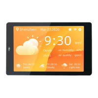
The board features a 3.5-inch LCD screen with a resolution of 320x480 and a capacitive touch panel that supports two-point touch. The LCD display interface uses SPI, connected to the ESP32's hardware HSPI interface, with an operating clock frequency up to 80MHz. The screen parameters include a pixel density of 165PPI and model WT-352215-A2.
Power management is handled by two LDOs providing 3.3V output to the board and external expansion boards. An external power interface is reserved to prevent interference with the ESP32's power supply. The board also includes a RST Key for resetting the device.
A Universal USB-C interface (Type-C) is used for power supply, UART communication, and firmware download. The hardware download circuit implements data flow control, enabling one-click automatic firmware download.
The board offers expansion capabilities through two 2.0mm pitch, 2x20Pin expansion board interfaces (interfaces 8 and 9). These interfaces are connected Pin to Pin, allowing for flexible installation of expansion boards in different directions. If the IOs of two expansion boards do not conflict, both can be inserted simultaneously to achieve dual expansion functions.
Indicators include a red power indicator that lights up when the USB cable is plugged in, and TXD/RXD indicators for UART communication that flash when data flows.
| Brand | Wireless-tag |
|---|---|
| Model | WT32-SC01 |
| Category | Motherboard |
| Language | English |