Pag. 14
MRK950 dual true diversity receiver
LINK / ACT.
USB
OUTPUT 90-264V
~
INPUT 90-264V
~
47-63Hz
60W MAXUNSWITCHED - 5A MAX
FUSE 2A-T
MRK950
LINK
100 Base T
ANTENNA
B
GPI
COM LINE LINECOM
LINE MIC LIFT GND LINE MIC LIFT GND
ANTENNA
A
LINE MIC LIFT GND LINE MIC LIFT GND
RX1
RX2
balanced
unbalanced
RF + DCRF + DC
12Vdc
200mA MAX
LINE
GPI
unbalanced
LINE
12Vdc
200mA MAX
balanced
balanced
balanced
AES/EBU WORD CLK
IN
OUT
75 Ω
HI-Z
21 3
4
5 6 7 8 9 10
11 12
13 14 15
161718
192021
2223
24
25
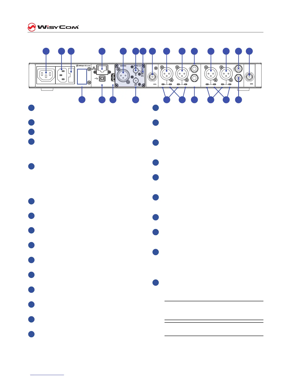
1
Mains output. Do not connect more than 8
units.
2
Mains socket input.
3
Mains fuse (2A-T).
4
Ethernet connector RJ45 for LAN connection of
the receiver. The leds on the connectore indi-
cate the status of the connection (Link and Ac-
tivity). (Optional)
5
AES/EBU XLR 3 pin output connector, digital
audio output transformer isolated, balanced.
This is part of the AES/EBU optional board, to-
ghether with 6, 7 and 22. Here it is possible to
install different option like Ethersound© I/O.
(Optional)
6
Word clock input for external syncronization of
digital audio output.
7
75 ohms termination switch for word clock in-
put.
8
Antenna B input, BNC connector, DC output for
booster power supply.
9
XLR 3 pin male connector, COM audio output of
the receiver 2, balanced. (Optional)
10
XLR 3 pin male connector, LINE audio output of
the receiver 2, balanced.
11
GPI output of the receiver 2, 1/4” (6,3mm) ste-
reo jack socket. (Optional)
12
XLR 3 pin male connector, COM audio output of
the receiver 1, balanced. (Optional)
13
XLR 3 pin male connector, LINE audio output of
the receiver 1, balanced.
14
GPI output of the receiver 1, 1/4” (6,3mm) ste-
reo jack socket. (Optional)
15
Antenna A input, BNC connector, DC output for
booster power supply.
16
Unbalanced LINE audio output of receiver 1,
1/4” (6,3mm) stereo jack socket.
17
Switches for shorting the pin 1 of the XLR con-
nectors of receiver 1 to the receiver ground or
not.
18
Switches for attenuating the audio output le-
vel on the XLR connectors. The attenuation is
30dB.
19
Unbalanced LINE audio output of receiver 2,
1/4” (6,3mm) stereo jack socket.
20
Switches for shorting the pin 1 of the XLR con-
nectors of receiver 2 to the receiver ground or
not.
21
Switches for attenuating the audio output le-
vel on the XLR connectors. The attenuation is
30dB.
22
Word clock output, for daisy chain connection.
BNC connector. (Optional)
23
LINK connection, for cascade connection of re-
ceivers, for remote control functionality. USB-A
connector.
24
USB-B connector for PC connection if this
MRK950 is a subnet controller. If this MRK950
is part of a subnet, this connector must be con-
nected to the LINK connector of the previous
MRK950.
25
Product identication label.
Note: shaded area represents the room for
digital audio outputs of the receiver. The pic-
ture shows the AES-EBU option installed.
MRK950EX has also “RF out” BNC’s for the
antenna splitting.
Rear panel
 Loading...