DRYWALL APPLICATIONS
After properly positioning the anti-tip bracket, use wall
anchors to fasten it to the wall. Using a Philips screwdriver
or a low rpm screw gun, drive the anchor into the surface
of the wallboard until the two cutting blades penetrate the
surface. Use gentle forward pressure to rotate the collar until
flush with the surface of the wall. Refer to the illustrations
below. Use #8 screws and flat washers to fasten the anti-tip
bracket to the wall.
IMPORTANT NOTE:
Pre-drill holes if difficulty is encoun-
tered during installation of the wall anchor. For hard wall-
board or double-board construction, use a 6 mm drill bit. For
solid plaster, use a 11 mm drill bit.
WOOD FLOOR APPLICATIONS
After properly positioning the anti-tip bracket, drill 5 mm pilot
holes through the floor. Use #12 screws and flat washers to
secure the bracket to the floor.
C ONCRETE FLOOR APPLICATIONS
After properly positioning the anti-tip bracket drill 10 mm
holes into the concrete a minimum of 38 mm deep. Use 10
mm wedge anchors to secure the bracket to the floor.
ANTI-TIP BOLT ADJUSTMENT
Once the bracket is secured in place, adjust the
anti-tip bolt
at the back of the range so the top of the washer is 22 mm
maximum from the floor. Slide the range into the opening and
verify the anti-tip bolt is engaged. Refer to the illustrations
below.
IMPORTANT NOTE:
The top of the range must be level.
Use the adjustable front legs and the rear casters to level
the range.
Raise the unit to its desired height by adjusting the front
legs and rear casters. The legs and casters allow for 54 mm
height adjustment. Use a 19 mm socket to adjust the rear
casters. The front legs are adjusted by rotating the bottom
hexagonal portion of the leg.
The anti-tip bracket can be installed by securing it to the wall
or floor using the supplied hardware.
Refer to the chart and illustration below to determine the
proper distance from the left side of the opening to the
anti-tip bracket. This will ensure the anti-tip bolt properly
engages the bracket.
MODEL A
762 mm Range 5 mm
914 mm Range 14 mm
1219 mm Range 5 mm
1524 mm Range 8 mm
ANTI- TIP BRACKET INS TALLATI O N
O VEN D OOR REINSTALLATIO N
IMPORTANT NOTE:
The oven door(s) should not be removed
unless it is necessary to fit the range through a tight
doorway. Door removal should only be done by a qualified
service technician or installer. Door removal and reinstalla-
tion may cause damage to the oven porcelain interior.
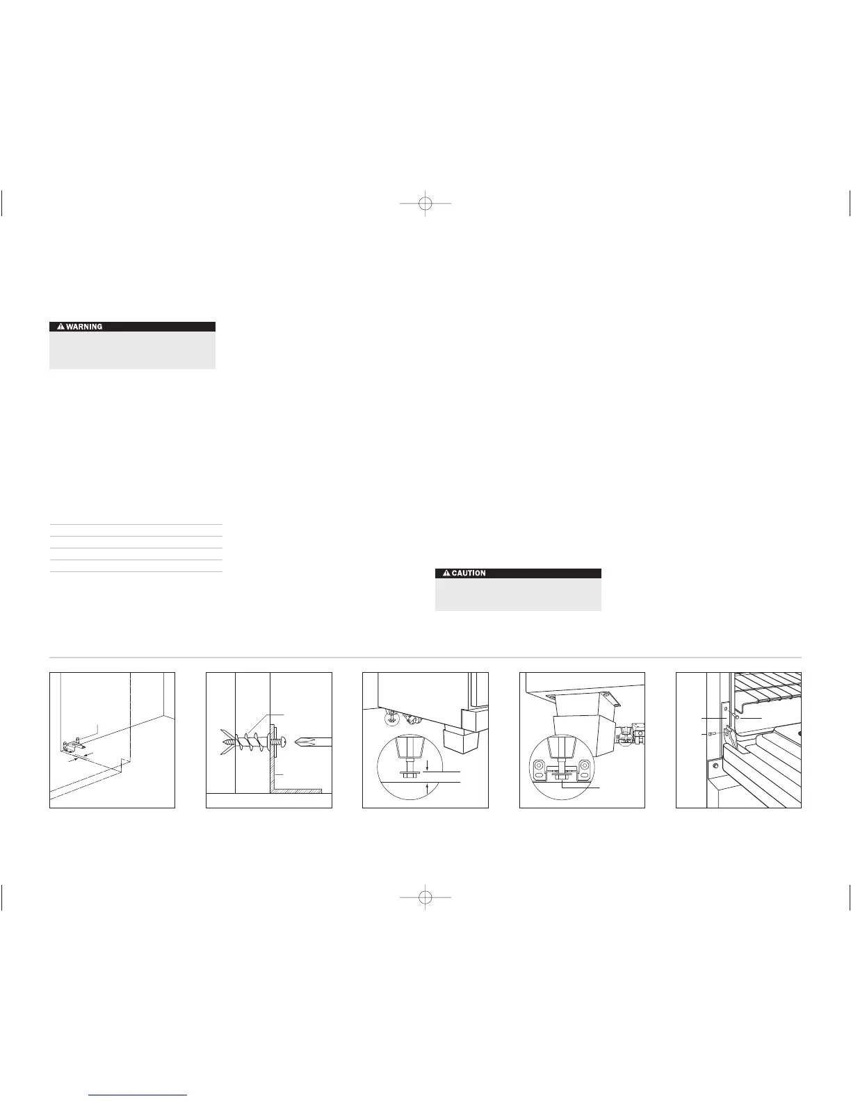
A
ANTI-TIP
BRACKET
Anti-tip bracket location.
ANTI-TIP
BRACKET
WALL
ANCHOR
Wall anchor installation.
22 mm MAX
ANTI-TIP
BOLT
Anti-tip bolt adjustment.
ANTI-TIP
DEVICE
ENGAGED
Anti-tip bolt engaged.
Hinge
Retainer
Plate
Upper Mounting
Screw
Hinge
Pin
Kickplate
Oven door reinstallation.
If oven door(s) have been removed, follow these steps to
reinstall:
1)
Hold the oven door on both sides and position it with
door hinges aligned with openings in the oven frame.
2)
Holding the oven door at an approximate 30° angle from
vertical, slide the hinges into the openings until the
bottom hinge arms drop fully into the hinge receptacles.
3)
Open the oven door to its fully opened position. Remove
the hinge pin from the appropriate hinge arm. Refer to
the
illustration below.
4)
Reinstall the hinge retainer plate with upper and lower
mounting screws.
5)
Open and close the door completely to ensure that it is
properly installed.
6)
For 1219 mm and 1524 mm ranges, complete these steps
for both oven doors.
7)
Reinstall the lower kickplate assembly.
IMPORTANT NOTE:
Fully extend the hinge claw which is
opposite the hinge pin location and insert into the hinge
pocket prior to inserting opposite side. This will ease the
installation of the oven door.
This range can tip. Injury to persons could result.
Install the anti-tip bracket supplied with the range.
Do not lift or carry the oven door by the door handle.
INSTALLATION INS TRUCTIONS
 Loading...