15
Step 6: Install Wiring
1) Run 120 VAC, 15 amp (minimum)
circuit electrical power cable from the
service panel to the junction box in
the rough-in plate.
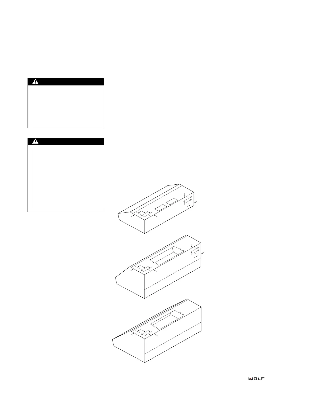
2) Remove the knock-out and install
the conduit connector on the rough-
in plate hole.
3) Feed the conduit through the hole
on top of the rough-in plate to the
junction box.
Before servicing or cleaning
unit, switch power off at service
panel and lock the service dis-
connecting means to prevent
power from being switched on
accidentally. When the service
disconnecting means cannot be
locked, securely fasten a promi-
nent warning device, such as a
tag, to the service panel.
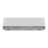
4) Remove the junction box cover
from the rough-in plate. Connect
black wire to power supply black
wire, white wire to power supply
white wire and green wire to green
wire or bare wire.
5) Place all wiring connections inside
junction box and re-install on rough-
in plate. Make sure that wires are
secure and that no wires are pinched
between cover and box.
Wiring Diagram
Refer to the wiring diagram packaged
with the hood for more information.
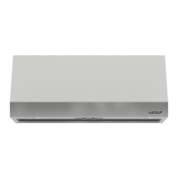
Step 7: Install Hood Filters and
Drip Cups
1) Remove all packaging material
from filters and drip cups.
2) Slide drip cups along bottom edge
of hood opening so lip overhangs
slightly.
3) Lift filters into place. Lines of filters
must run vertically and align with
drip cups.
4) Adjust filters to fill space by sliding
filters left to right.
Final Installation
If the Wolf logo nameplate is to be
applied to the hood, refer to page 18
for installation steps.
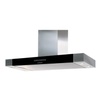
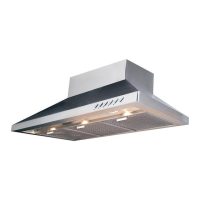
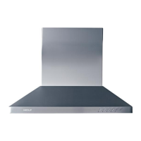
P RO S ERIES W ALL H OODS
This ventilation hood must be
properly grounded. This unit
should be installed by a quali-
fied electrician in accordance
with all applicable national
and local electrical codes.