Do you have a question about the Wolf V Series and is the answer not in the manual?
Outlines the purpose and scope of the service manual for technicians.
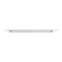
Explains the coding system used for V Series ventilation models and their features.
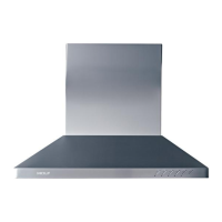
Details the location and importance of the product rating plate for identification.
Points to external resources for comprehensive model details and accessory listings.
Guides users to find essential product documentation and installation manuals online.
Instructions for removing the filter from the cooktop hood.
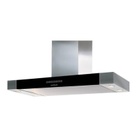
Steps to remove the filter cover, specifically for black hood models.
Procedures for correctly installing the filter back into the hood.
Guidance on how to remove the LED light assembly from stainless steel models.
Steps for installing the LED light assembly into stainless steel hoods.
Instructions for safely removing the control assembly from the hood unit.
Steps for correctly installing the control assembly into the hood.
Explains how to access the internal area above the hood's main cube component.
Detailed steps for removing the power board assembly from the unit.
Procedures for reinstalling the power board assembly into the hood.
Instructions for safely removing the transformer component.
Steps for correctly installing the transformer component.
Guidance on how to remove the inner panel magnet.
Steps for installing the inner panel magnet correctly.
Instructions for removing the inner panel of the hood.
Steps for reinstalling the inner panel into the hood.
Guidance on how to remove the inner panel hinge components.
Steps for installing the inner panel hinge correctly.
Instructions for removing the side panel (field-replaceable on some models).
Steps for installing the side panel.
Instructions for removing the outer panel of the hood.
Steps for installing the outer panel onto the hood.
Guidance on removing the hood's mounting bracket.
Steps for installing the hood's mounting bracket.
Steps for removing the lower mounting bracket.
Steps for installing the lower mounting bracket.
Instructions for removing the damper from the hood's discharge.
Steps for installing the damper onto the hood's discharge.
Detailed steps for removing the wire harness from the unit.
Procedures for installing the wire harness correctly.
Steps to pair the remote control with the hood unit.
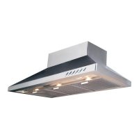
The Wolf V-Series Cooktop Hoods Service Manual provides comprehensive information for troubleshooting, diagnosing malfunctions, completing repairs, and returning the product to proper operational condition. This guide is specifically intended for use by Factory Certified Service personnel, as Wolf Appliance, Inc. recommends that repairs be performed only by authorized service companies. The manual emphasizes safety throughout, with prominent Warning and Caution labels indicating potential hazards that could lead to serious injury, death, or product damage if precautions are not followed. These labels are strategically placed at the beginning of sections and where specific risks are present.
The manual begins with general information, including a service manual introduction that outlines its purpose. It also details the product rating plate information, which is crucial for identifying specific unit details. For Ceiling-Mounted Hoods, the rating plate is conveniently located behind the rightmost filter, accessible by opening the center panel and removing the filter. Key information found on the rating plate includes the model, serial number, and electrical specifications such as current draw. Additionally, the manual directs users to the Wolf Distributor Price List for detailed model descriptions and compatible sales accessories, and to the Product Specifications and Manuals Library for Product Use and Care Guides, Installation Guides, and other product specifications.
The warranty information is also covered, explaining that product warranty is determined by the installation location and date. Users can view product warranties and search for warranty and service information by serial number, customer last name, and address using the provided links to the Sub-Zero service website. Warranties commence on the day of product installation.
A significant portion of the manual is dedicated to component access and removal, providing step-by-step instructions for servicing a Wolf Ceiling-Mounted Hood. Safety is paramount in this section, with a Warning emphasizing the need to disconnect power to the hood before servicing any electrical components to avoid electric shock. It also cautions that removing a hood from its installation is a heavy task requiring two persons and should only be performed by an authorized service technician or installer. A Caution advises careful handling of sheet metal parts due to sharp edges.
The manual details the process for filter removal, which involves pushing a plastic tab on the front end of the filter toward the rear of the hood and gently pulling it down, then pulling the filter forward to remove it. Filter installation is the reverse process, placing the filter in the opening bottom first and rotating it upward into place. For black hoods, specific instructions are provided for removing the filter cover, which involves opening it to 90 degrees, pressing a hinge release pin toward the center of the hood, disengaging it, and then sliding the cover to the right to disengage the pin from the other hinge.
LED light removal for stainless steel models is also covered, noting that hood lights are LED fixtures that must be replaced as assemblies. The process involves using a flat-head screwdriver to pry the LED light assembly away from the stainless steel panel, followed by a Phillips screwdriver to remove the diffuser sleeve. The LED light wire harness is then pulled through a hole to access and disconnect the connector, allowing the assembly to be removed. Installation is the reverse, connecting the wire harness, positioning the assembly on the frame, and snapping it into place.
Control assembly removal and installation are meticulously described. Removal involves using a Phillips screwdriver to remove screws holding the assembly to the frame, a flat-head screwdriver to remove the wire cover on the rear of the control panel, disconnecting the wire harness, and then removing the assembly. Installation follows the reverse order, connecting the wire harness, installing the wire cover, placing the assembly so buttons align with frame holes, and securing it with screws.
Accessing the area above the Easy Cube is explained, as this is where the power board assembly, light transformer, and other electrical components are mounted. For internal blower models, the blower is also located inside the Easy Cube. The process involves removing two screws at the bottom of the lower chimney, raising and blocking it for island hoods, or removing it for wall hoods. The manual notes that the lower chimney should not be secured to the wall.
Power board assembly removal and installation are detailed, including opening the ribbon cable cover, disconnecting the ribbon cable, removing screws holding the case to the unit, separating the case halves, disconnecting wire harnesses from the power board, and then removing the assembly. Installation reverses these steps.
Transformer removal and installation instructions are also provided, involving disconnecting wire harnesses and connectors, removing screws holding the transformer to the power board assembly case, and then removing the transformer. Installation reverses these steps.
Inner panel magnet removal and installation are covered, requiring a combination wrench to hold the magnet anchor while turning the magnet counterclockwise to remove it, and clockwise to install it. Inner panel removal and installation involve pulling on the magnet side to open it, removing hinge screws with a Phillips screwdriver, and supporting the panel from underneath during removal. Installation involves placing the panel over hinges and installing screws.
Inner panel hinge removal and installation are also described, including removing the central pin, hinge leaf from the unit, and countersunk screws holding the hinge to the frame. Installation reverses these steps.
Side panel removal and installation are mentioned specifically for white glass models, which have field-replaceable side panels. Outer panel removal and installation involve removing screws around the outside of the panel with a Phillips screwdriver and lifting it off. A tip suggests pushing one corner upward to loosen a tight outer panel.
Mounting bracket removal and installation are detailed, involving removing screws and then removing the bracket. Installation involves installing the brackets to the hood using specified length screws and determining the height based on support framing height.
Damper removal and installation involve removing duct sealing tape and pulling the damper from the round discharge. Installation reverses these steps, placing the damper on the round discharge and securing it with duct sealing tape.
Wire harness removal and installation are extensive, covering disconnection of LED light wire harnesses, removal of control assembly screws and wire cover, disconnection from the control panel, opening the ribbon cable cover and disconnecting the ribbon cable, removing power board assembly screws, disconnecting wire harnesses from the power board assembly, removing J-box cover screws, disconnecting from the J-box, and disconnecting from wire clips around the inner panel perimeter. Installation reverses these steps.
Finally, the manual includes instructions for pairing the remote control, which involves verifying new AAA batteries, ensuring the blower and lights are off, and then pressing and holding the "I" button on the hood for five seconds until the LED flashes twice, indicating successful pairing.
The troubleshooting guide section explains how to address various components in a Wolf Ceiling-Mounted Hood. It reiterates the Warning about disconnecting power before tests and exercising care when performing tests with the hood energized. It also repeats the Warning about the weight of the units if removal from installation is necessary. The troubleshooting table provides symptoms, diagnostic tests, and resolutions for common issues such as a non-functioning remote control, hood lights and blower not energizing, blower motor running only at high speed, hood lights not working, and blower motor not running at all. It also addresses issues with internal, external, and inline blower motors, and insufficient airflow. The diagnostic tests often involve checking voltage at various points (J-box, electrical box, power board, transformer), ohm-ing out connectors, and verifying ribbon cable connections. Resolutions typically involve replacing batteries, repairing electrical connectors or wires, replacing power boards, LED light assemblies, harnesses, or transformers, and correcting ducting issues. For airflow problems, it suggests checking filters and make-up air.
Technical data for VC36/48 S/W models is provided, including AC power, min/max ceiling height, convertibility to ductless/recirculating (kit sold separately), and hood width/depth for VC36 and VC48 models. Fan modes are detailed with CFM, noise (sones), and power (W) for each of the four settings: 1, 2, 3, and Boost.
Basic wiring diagrams explain the electrical flow within the hood. 115 VAC enters through the junction box and plugs into the electrical box, connecting to the power board via a three-wire harness. For internal blowers, 115 VAC is sent from the power board to the blower. For inline and remote blowers, 115 VAC is sent to a terminal block where the blower connects. Blower speed is controlled by a triac on the power board assembly. Voltage for the touch control travels through the ribbon cable harness from the power board to the hood body. 115 VAC is supplied to the light transformer, which converts it to 12 VDC for the LED assemblies. The orange wires carry 120 VAC to the primary side of the transformer, while the wire sheath contains 12 VDC for the hood lights. The connector with gray, black, and white wires provides 12 VDC to the touch control. A detailed VC36/48 W/S wiring diagram is also included, with a Warning about the information being for qualified service personnel only, emphasizing disconnection from electrical supply before service, and ensuring all grounding devices are connected to prevent severe electrical shock.
| Lighting | LED |
|---|---|
| Finish | Stainless Steel |
| Construction Material | Stainless Steel |
| Ventilation Type | Ducted |
| Width Options | 30", 36", 42", 48", 54", 60" |
| Blower Options | Internal, Remote |
| Control Type | Touch |
| Blower CFM | 300 to 1500 CFM |
| Filters | Baffle |
| Number of Blower Speeds | 4 |