EasyManua.ls Logo

Wolo OCEAN ALERT 170 - User Manual

Default Icon
4 pages
Print Icon
To Next Page IconTo Next Page
Loading...
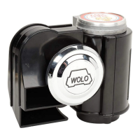
Your purchase of a Wolo OCEAN ALERT
®
Air Horn will complement your boat while offering an extra level
of protection. Wolo’s products are manufactured with the finest materials. Before being packaged, each horn
is tested to ensure it meets all of our manufacturing specifications. If you need help installing your new Wolo
horn, our technicians are available to answer your questions, Monday thru Friday, 9 AM to 4 PM EST at
1-888-550-HORN (4676).
Before installation of the horn is attempted, it is important to read these instructions completely. The lives of
people can be dependent on a proper installation of the horn. The person doing the installation must have
knowledge of the proper method for mounting and securing the horn to the exterior of the boat as well as
knowledge of the boat’s electrical system. Again, read the instructions completely and note any messages
marked “IMPORTANT” or “WARNING’’. A safe installation will prevent injury or damage to the boat.
WARNING: Installation of the OCEAN ALERT requires drilling. The installer must carefully inspect both sides
of the selected mounting locations to ensure that there are no wires, fuel lines and or any other components
that could be damaged by drilling.
WARNING: If any wires are routed through drilled holes; always de-burr, ensuring that there are no sharp
edges. Install a rubber grommet into all metal holes that wires are being routed through.
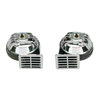
MOUNTING TRUMPET: Fig. 1 & 2
IMPORTANT: The horn should be mounted facing forward
whenever possible. The NMMA Certification Program requires
this for boats 39’ or longer.
1. Locate the desired mounting location of the trumpet. For
best results, the front of the horn should be unobstructed so
that the sound can carry straight ahead.
IMPORTANT: FOR BEST PERFORMANCE AND SOUND,
ALWAYS MOUNT THE COMPRESSOR CLOSE TO
TRUMPET, KEEPING THE HOSE LENGTH AS SHORT AS
POSSIBLE. THE COMPRESSOR MUST BE MOUNTED IN A
DRY INTERIOR LOCATION).
2. Use the horn’s gasket as a template, mark hole locations
and drill to size.
3. Thread the two chrome air inlet tubes into the base of the
horn.
4. Mount and secure the horn as shown in Fig. 1. IMPORTANT:
Be sure to use the rubber gasket provided to protect against
water leaks. Tighten the base plate nuts that thread onto air
inlet tubes evenly to ensure a watertight seal.
5. Position the front trumpet support bracket around the narrow
part of each trumpet. Push the bracket forward until it is tight.
Using the bracket as a template, mark hole locations and drill
to size, see fig 2.
6. Secure the front trumpet support bracket using the hardware provided. Tighten screw to ensure a watertight
seal.
IMPORTANT: Provided in the kit are two soft rubber strips that are placed into the ring of the support bracket to
provide a tight fit and prevent vibration. Be sure to use the rubber gasket provided to protect against water leaks.
INSTALLATION INSTRUCTIONS
Model 170 OCEAN ALERT
®
12-Volt
air
inlet
tubes
Question and Answer IconNeed help?

Do you have a question about the Wolo OCEAN ALERT 170 and is the answer not in the manual?

Summary

Installation Instructions

Mounting the Air Horn Trumpet

Instructions for locating, marking, drilling, and securing the air horn trumpet and support bracket to the boat.

Compressor Installation

Guidance on installing the compressor in a dry interior location, connecting tubing, and ensuring proper airflow.

Wiring: New Horn Button Switch

Diagram and steps for wiring the horn relay, compressor, and horn switch using a new button.

Wiring: Using Factory Horn System

Instructions for integrating the horn relay with the boat's existing factory horn wiring system.

Product Warranty and Service

Obtaining Warranty Service

Procedure for returning the product for warranty repair or replacement, including required documentation and fees.

Overview

The Wolo Model 170 OCEAN ALERT® is a 12-volt air horn designed for marine use, providing an extra level of protection for boats. It is manufactured with high-quality materials and undergoes testing to ensure it meets manufacturing specifications.

Function Description:

The OCEAN ALERT® air horn produces a loud sound for signaling and safety on the water. It operates using a compressor that forces air through two trumpets. The horn is designed to be mounted on the exterior of a boat, with the compressor installed in a dry interior location. It can be integrated with a new horn button switch or connected to a boat's existing factory horn system (two-wire system) using a supplied relay.

Important Technical Specifications:

  • Power Requirement: 12-volt DC.
  • Fuse Requirement: A 20-amp inline fuse is required for the power circuit, connected directly to the power source.
  • Wire Gauge (Compressor to Relay): 16-gauge or heavier for positive (+) and negative (-) connections.
  • Wire Gauge (Relay to Horn Switch): 18-gauge or heavier.
  • Compressor Mounting Distance: Must be installed no further than 30 inches from the trumpet for optimal sound performance.
  • Compliance:
    • Meets U.S. Coast Guard's C.O.L.R.E.G.S. and U.S. Inland Navigation Rules, Annex III Regulations for boats up to 20 meters / 65 ft.
    • NMMA (National Marine Manufacturers Association) "type accepted."
    • Meets American Boat & Yacht Council (ABYC) A-23 standard for boats up to 20 meters / 65 ft.

Usage Features:

  • Mounting:
    • Trumpet: Should be mounted facing forward whenever possible, with the front unobstructed for optimal sound projection. A rubber gasket is provided to ensure a watertight seal when mounting to the surface. Two chrome air inlet tubes thread into the horn's base. A front trumpet support bracket is used to secure the trumpets, with soft rubber strips inserted into the bracket ring to prevent vibration and ensure a tight fit.
    • Compressor: Must be installed in a dry interior location, close to the trumpet (within 30 inches) for best performance. It can be mounted vertically with the air outlet on top. A 3/16" hole is drilled for securing the compressor using a bolt, lock washer, and nut.
  • Air Tubing: Plastic tubing connects the compressor to the two air inlets via a "Y" connector. It should be cut to size and kept as short as possible. Kinks or sharp bends must be avoided to prevent reduced airflow and altered horn sound.
  • Electrical Connections:
    • New Horn Button Switch (Fig. 5):
      • A horn relay is provided and must be installed in a dry interior location with terminals facing downward.
      • Relay terminal 87 connects to the compressor's positive (+) terminal.
      • Relay terminal 85 connects to the horn button switch (not provided).
      • The horn switch's other terminal connects to a negative (-) source (battery post or clean metal surface).
      • Relay terminals 30 & 86 connect to a positive (+) 12-volt source (battery, alternator, fuse block) with a 20-amp inline fuse, connected directly to the power source.
      • The compressor's negative (-) terminal connects to the boat's negative (-) battery post or a clean metal negative surface.
    • Factory Horn System (Two-Wire System) (Fig. 6):
      • The supplied relay must be used to protect the factory horn button switch and wiring.
      • The two wires from the factory horn are removed.
      • Relay terminal 85 connects to one factory horn wire.
      • Relay terminal 86 connects to the other factory horn wire.
      • Relay terminal 30 connects to a positive (+) 12-volt source (battery, alternator, fuse block) with a 20-amp inline fuse, connected directly to the power source.
      • Relay terminal 87 connects to the compressor's positive (+) terminal.
      • The compressor's negative (-) terminal connects to the boat's negative (-) battery post or a clean metal negative surface.
  • Safety Warnings:
    • Thoroughly read all instructions before installation.
    • Carefully inspect mounting locations for wires, fuel lines, or other components that could be damaged by drilling.
    • De-burr all drilled holes and install rubber grommets if wires are routed through metal holes.
    • Ensure the 20-amp inline fuse is connected directly to the power source.

Maintenance Features:

  • Warranty: Wolo Manufacturing Corporation provides a twelve-month warranty from the date of purchase, covering defects in workmanship and materials. If a defect is proven, Wolo will repair or replace the item free of charge if returned within twelve months with proof of purchase. The warranty is limited and does not cover damage from neglect, abuse, abnormal use, modifications, faulty installation, or natural causes.
  • Warranty Service: To obtain service, return the product prepaid with the original bill of sale, a brief description of the problem, and a check or money order for $10.00 to cover return shipping.
  • Technical Support: Technicians are available Monday through Friday, 9 AM to 4 PM EST, at 1-888-550-HORN (4676) for installation assistance.

Wolo OCEAN ALERT 170 Specifications

General IconGeneral
BrandWolo
ModelOCEAN ALERT 170
CategoryHorn
LanguageEnglish

Related product manuals