7
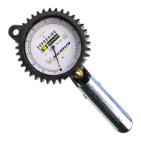
INFLATOR GAUGE
WONDER SPA
CONTENTS
•1inatorgauge
•1 hose
1
•Calibrationcerticate
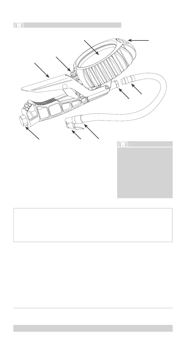
Lever
Dial
Hole
Handle
Discharge valve
Connector of the hose
End connector
Connection
Threaded metallic
attachment
A -
B -
L -
M -
S -
W -
X -
Y -
z -
PHASE 1
1. To mount the hose in the package, screw the hose connector (W) onto the
inatorgaugeconnection(Y)byhanduntilitcomesintocontactwiththe
gasket,thentightenafurther¼turnusingonlya12mmspanner.
2. Connectandtightentheotherendoftheinatorgaugetothecompressor
or other source of compressed air/nitrogen using the ¼ GAS (Z) brass
threaded connection.
1
n. 1961 (150 cm) for standard valves − n. 1971 (60 cm) for standard valves (unique and
exclusive equipment of n. 1997) − n. 1961/3 (300 cm) for standard valves (optional on request)
Thenotesandtechnicalspecicationsinthis
manual are valid for the products listed below,
unlessotherwisespecied:
• Superdainuinatorgauge;
• 1999inatorgauge;
• Eurodaimoinatorgauge;
• 2014inatorgauge;
• 1997inatorgauge.
L
B
S
M
Z A X
Y
W
Onceyouhaveremovedtheitemsfrom
the box, please check that the product
and its components are complete and
without any visible damage that could
have occurred during transport.