8
INFLATOR GAUGE
WONDER SPA
3. Checkthattheinatorgaugeisinworkingorderbysqueezingthehandle
(M)andrmlyholdingtheendofthehose(X)toavoidsuddenmovement
ofthehosecausedbythepressureofairornitrogen.
4. Verifythattheairorgasonlyowsthroughtheconnector(X)andthereare
no leaks from the other connections.
PHASE 3
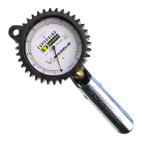
Oncethegaugeisconnectedtothetyrevalve(asdescribedinPHASE2),
with the handle in resting position (M), the dial pointer (B) will indicate the
pressurevaluedetectedinthetyre.
Squeezethehandle(M)tointroduceair/nitrogenintothetyrethroughthe
valveandinatethetyre.Inationwillstopifthehandleisreleased.
PHASE 2
1. If present, unscrew the protective valve cap.
2. Toattachtheconnection(X)oftheinationhose,presslever(A),insertthe
opening of the connection onto the threaded part of the valve and press
axiallytoavoiddamagingthevalve-thenreleaselever(A)toanchorthe
connectiontothethreadofthevalve.Completetheoperationbyturning
theconnectiononehalf-turnclockwiseinordertocorrectlycompressthe
gasket of the connection itself.
WARNING
To avoid damage or injury, directthe airow away frompeople,
animals or objects before squeezing the handle.
WARNING
This connection opens a mechanism inside the valve to allow the
passage of air or nitrogen through the pressure gauge, from the
sourcetothe tyreandviceversa.Ensure thatnoleaksofairor
nitrogen are present at the connections as this could cause the
inatorgaugetogiveafalsereading.
WARNING
•Hold the connection (Z) rmly using a 16mm spanner when
tightening to the compressor or air source to avoid accidental
breakage of the gauge.
•Ensure that there are no air or nitrogen leaks due to incorrect
installationoftheinletandoutlethosefromtheinatorgauge.
Theinatorgaugecanbehungusingthehole(L)thatislocatedat
the top of the rubber protection.