Dealer Service 29
MAN1280 (4/05/2019)
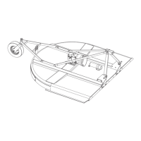
NOTICE: There are two locations for the jack stand.
Mount to tongue tube for storage and on “Y” section
during operations.
5. Install tongue adjustment channel between mast
plates with 5/8” bent pin and retain with hair pin
clip.
6. Install hitch with 5/8” x 6-1/2” bolt, safety chain,
thick plated washer, and 5/8” lock nut. 3/4” x 4-3/4”
pin should be installed during operation; removal of
pin can provide additional adjustment to attach to
prime mover.
7. Install hose holder over tube with 5/8” x 3-3/4” bolt
and lock nut approximately 14” from the hitch. DO
NOT COVER DECALS.
8. Remove Primary seed box divider and front tray.
See Figure 30. Ensure front tool is in a forward
position to avoid interference during installation.
Refer to page 11 for front tool adjustment.
9. Secure 5/16” x 1” carriage bolt on frame stiffener
with push-on washer; this will be used to secure
hydraulic hoses. Install frame stiffener using 3/8” x
1” carriage bolts and lock nuts.
10. Align hydraulic cylinder mount with slots on z-plate,
at the rear of the seeder. Mount using 3/8” x 1-1/4”
bolts and lock nuts.This mount connects the
seeder frame and frame stiffener previously
installed.
11. Open lower chain shield to install left mounting
bracket. Left and right mounting brackets use four
3/8” x 1” carriage bolts and lock nuts.
NOTICE: If cultipacker option is installed, remove culti-
packer stops. Mounting brackets contain cultipacker
stops within design.
■ Loosen jam nuts on cultipacker spring rods
until springs are unloaded before removing spring
stops.
12. Align the pivot arm tubes with mounting brackets.
Mount using 5/8” x 3-3/4” bolts and lock nuts. Do
not over-tighten.
13. Connect hydraulic cylinder to cylinder mounting
bracket and pivot arm using pin provided with
cylinder and 1” x 4” pin, respectively. Cylinder lock
aligns with mounting location on pivot arm. Secure
in unlocked position with 5/8” bent pin and hair pin
clip.
14. Mount wheel arms to pivot tube using 1/2” x 4”
bolts and lock nuts.
NOTICE: Install wheel arms to an outside most posi-
tion. Instability during transport can occur if heel arm
spacing is narrow.
15. Install tires to wheel arms with 3/4” washer, castle
nut, and cotter pin. Install hub caps.
16. Install the SMV mount and sign to pivot arm tube
with 1/4” x 3/4” bolts and nuts.
NOTICE: SMV sign should be mounted to the center
most position possible on the implement.
17. Install two 3/8” NPT to 9/16” JIC adapter to cylinder
ports. Install four 9/16” JIC to 3/4” ORB adapters to
relief valve ports. Mount valve to left side mast
plate using 5/16” x 2-1/2” bolts and nuts.
18. Route 54” hoses from cylinder to valve. Mount to
frame stiffener with butterfly clamp and secure with
5/16” nut.
19. Route 94” hoses from valve to hitch. Install 1/2”
NPT to 9/16” JIC adapters and quick couplers to
tractor side.
20. Reinstall primary seedbox divider, front tray, and
close lower chain shield.
(Rev. 8/20/2019)