20 Owner Service
15914 (Rev. 3/23/2007)
NOTICE
■
If blade pin is seized in crossbar and extreme
force will be required to remove it, support cross-
bar from below to prevent damage to spindle.
Your dealer can supply genuine replacement
blades. Substitute blades may not meet original
equipment specifications and may be dangerous.
Blade Installation
Always replace both blades at the same time to main-
tain balance.
Liberally coat blade pin and crossbar hole with Never-
Seez® or equivalent. Make sure blade is offset away
from deck and cutting edge is positioned for counter-
clockwise rotation.
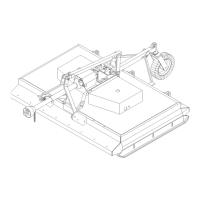
Install blade pin (9) up through blade (8) then through
hole in crossbar and push firmly against crossbar (7).
Install as many spacers (4, 5 or 6) as possible and still
be able to slide keyhole plate (3), with ears up as
shown, into blade pin groove. Place blade pin clip (2)
over keyhole plate and into blade pin groove. Secure
with bolt (1). Repeat for opposite blade. See Figure 7.
Blade should be snug but swivel on pin without exces-
sive force. Retain any spacers not used in installation
for use when blade wears or on future installations.
Blade Sharpening
Always sharpen both blades at the same time to main-
tain balance. Follow original sharpening pattern. Do not
sharpen blade to a razor edge. Leave from a 1/16" to
1/8" blunt edge. Do not sharpen back side of blade.
Belt Installation
One of the major causes of belt failure is improper
installation.
Before new belts are installed, check pulley shafts and
bearings for wear. Check pulley grooves for cleanliness
and wear. Be sure they turn freely and with only slight
wobble. If grooves require cleaning, moisten a cloth
with a non-flammable, non-toxic degreasing agent or
commercial detergent and water.
Figure 9. Belt Routing
Avoid excessive force during installation. Do not use
tools to pry belt into pulley groove. Do not roll belt over
pulleys to install. This can cause hidden damage and
premature belt failure. Always loosen idlers when
installing belts.
The drive on this cutter uses three belts. They are a
matched set and must be replaced as such.
Remove belt shields.
Loosen nut on idler adjustment rod (located on right
side of gearbox stand) as loose as possible.
Remove old belts and install new ones. Tighten nut on
idler adjustment rod. Belts should be very tight.
NOTICE
■
Check tension on new belts every half hour
the first four hours of operation and then every
eight hours.
CHAIN SHIELDING
Full chain shielding must be installed when
operating in populated areas or other areas where
thrown objects could injure people or damage
property.
• If this machine is not equipped with full chain
shielding, operation must be stopped when any-
one comes within 300 feet (92 m).
• This shielding is designed to reduce the risk
of thrown objects. The mower deck and protec-
tive devices cannot prevent all objects from
escaping the blade enclosure in every mowing
condition.
It is possible for objects to ricochet
and escape, traveling as much as 300 feet (92 m).
Inspect chain, rubber, or steel band shielding
before each use. Replace if damaged.
DB967