12 Operation
MAN1177
(
07/28/2023
)
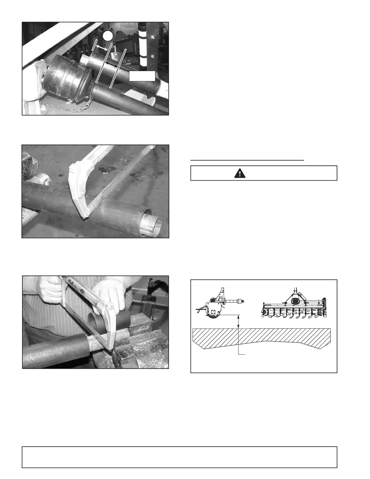
Figure 4. Determine Shield Length
5. Cut the upper shield to this overall dimension.
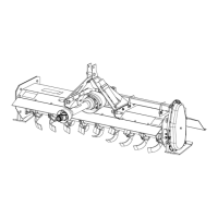
Figure 5. Cut Shield
6. Place the cut portion of the shield against the end of
the shaft and use as a guide. Mark and cut the shaft.
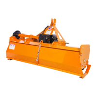
Figure 6. Cut Shaft to Length
7. Repeat step 6 for the other half of the drive.
8. File and clean the cut ends of both drive halves.
Ensure the drive halves slide smoothly together.
Do not run the tractor if proper driveline engagement
cannot be obtained through these methods.
Connect the driveline to tractor PTO shaft, making sure
the spring-activated locking collar slides freely and
locks driveline to PTO shaft.
■ If attaching with quick hitch, the distance be-
tween the tractor PTO and gearbox input
shaft will increase. Please follow the steps as
you would for a 3-point hitch to insure proper
engagement.
WORKING DEPTH ADJUSTMENT
■ Keep all persons away from operator control
area while performing adjustments, service, or
maintenance.
1. Raise the tiller off the ground.
2. Level tiller side to side. Check by measuring from
the forward skid shoe pivot to the ground on each
side. (Figure 7)
3. Adjust, using tractor 3-point arm leveling device.
NOTE: Keep the front of the tiller parallel to the
ground.
4. Place two jack-stands under the tiller rotor shaft.
Figure 7. Leveling the Tiller
5. Loosen the 1/2" cap screws that act as the front piv-
ots to the skid shoes. Remove the 1/2" cap- screws
(46) that hold the rear of the skid shoes to the tiller
frame.
6. Adjust the skid shoe to the desired tilling depth
(Figure 8). Reinstall the cap screws in the rear of
the skid shoe and tighten all cap screws.
NOTICE
WARNING
MEASURE BOTH
ENDS TO GROUND
PARALLEL TO GROUND
CD8615
A
1-1/2"