What to do if the engine does not start by pressing the start button on Woodward Control Panel?
J
James AllenAug 25, 2025
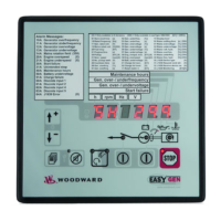
If the engine won't start when you press the "Start" button on your Woodward Control Panel, ensure the unit isn't in "Stop" mode, indicated by the lit "Stop" LED. If it is, press the "Operating Mode" button twice to switch to manual mode.