Home
Woodward
Control Systems
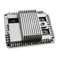
ECM3
Woodward ECM3 - User Manual
98 pages
Manual
Specs
Ask a question
Save Page as PDF
To Next Page
To Next Page
Loading...
EC
-
US
-
L1
Product Manual 26348
(Revision E
,
01
/2022)
Original Instructions
ECM3
Electronic Fuel Injection Control
Installation and Operation Man
ual
Released
2
Table of Contents
Main Page
default chapter
3
Table of Contents
3
Warnings and Notices
6
Electrostatic Discharge Awareness
8
Regulatory Compliance
9
Chapter 1. General Information
11
Introduction
11
Control Specifications
12
Figure 1-1. ECM3 Outline Drawing
14
Chapter 2. Installation
15
Introduction
15
General Installation Notes and Warnings
15
On-Engine Mounting
16
Figure 2-1. Vibration Isolator Installation
17
Temperature Specifications
18
Figure 2-2. Mounting Hole Layout
18
Electrical Connections
19
Grounding for Protection against Electrical Shock
20
Grounding for Protection against Electrical Noise
20
Harsh EMC Environmental Guidance
22
Figure 2-3. I/O Isolation
22
ECM3 Wiring Diagrams
23
Input Power
26
Figure 2-4. Input Power Wiring Diagram
29
Figure 2-5 Duty Cycle
31
Figure 2-6. MPU Wiring Diagram
31
Figure 2-7. MPU Signal Arm and Trigger
32
Figure 2-8. MPU Wired Correctly
32
Figure 2-9. MPU Wired Incorrectly
32
General Purpose Analog Inputs
33
Figure 2-10. Proximity Sensor Wiring Diagram
33
Figure 2-11. Current Input Wiring Diagram: Loop Powered
35
Figure 2-12. Current Input Wiring Diagram: Self-Powered
35
Figure 2-13. Voltage Input Wiring Diagram: Self-Powered
36
Engine Sensor Analog Inputs
37
Figure 2-14. Engine Sensor Analog Input Wiring Diagram
38
Temperature Sensor Analog Inputs
39
Figure 2-15. Temperature Sensor Analog Input Wiring Diagram
40
Boolean and PWM Inputs
41
Figure 2-16. Boolean Usage
42
Figure 2-17. PWM Usage
42
Figure 2-18. PWM Input Wiring Diagram
43
Figure 2-19. Boolean Input Wiring Diagram
43
Figure 2-20. Sourcing Input Wiring Diagram
44
Boolean and PWM Outputs
45
Figure 2-21. Sinking Input Wiring Diagram
45
Figure 2-22. PWM Output Wiring Diagram for L-Series, FCV, Flo-Tech
47
Figure 2-23. PWM Output Wiring Diagram for Proact Digital Plus
47
Figure 2-24. PWM Output Wiring Diagram for General Application
47
Figure 2-25. PWM Output Wiring Diagram for Linear Actuator
48
Figure 2-26. Boolean Output Wiring Diagram
48
Figure 2-27. Fuel Injection Group Design
50
Figure 2-28. Fuel Injection Output Wiring Diagram
52
Figure 2-29. RS-232 Wiring Diagram
54
Figure 2-30. RS-485 Wiring Diagram
56
Figure 2-31. CAN Cable Cross-Section
58
Figure 2-32. CAN System Wiring Example
58
Figure 2-33A. CAN-1 Wiring Diagram
60
Figure 2-33B. CAN-1 Wiring Diagram-On and off Engine
61
Figure 2-34A. CAN-2 and CAN-3 Wiring Diagram
61
Figure 2-34B. CAN-2 and CAN-3 on Engine Enhanced Wiring Diagram
62
Chapter 3. Serial Communications
63
Modbus Communication
63
Figure 3-1. ASCII/RTU Representation of 3
63
Port Adjustments
65
Chapter 4. Programming and Service Tools
66
Introduction
66
Connecting the ECM3 to a PC
67
Loading Woodward Software Tools on the PC
67
Applying Power to the ECM3
67
Toolkit Software Instructions
67
Figure 4-1. Connecting the ECM3 to a PC
67
Watch Window Software Instructions
72
Using Watch Window
75
Figure 5-1. Sensor Symbol Key
76
Figure 5-2. Pattern 1
77
Figure 5-3. Pattern 4
77
Figure 5-4. Pattern 2
79
Figure 5-5. Pattern 8
79
Figure 5-6. Pattern 3
80
Figure 5-7. Pattern 6
80
Figure 5-8. Pattern 7
81
Figure 5-9. Pattern 9
81
Figure 5-10. Pattern 5
82
Chapter 6 Product Support and Service Options
83
Product Support Options
83
Product Service Options
83
Returning Equipment for Repair
84
Replacement Parts
84
Engineering Services
85
Contacting Woodward's Support Organization
85
Technical Assistance
86
Appendix A. Connector Information
87
Recommended Wire Size and Types
88
Wire Gauge-AWG to Metric Comparison
89
Appendix B. Commissioning Procedure
90
Control I/O Commissioning
90
EFI Valve Commissioning
90
Appendix C. Proximity Sensors
91
Figure C-1. Prox Sensor Schematic
91
Appendixd Technical Specifications
93
Revision History
95
Declarations
96
Other manuals for Woodward ECM3
Installation Manual
100 pages
Need help?
Do you have a question about the Woodward ECM3 and is the answer not in the manual?
Ask a question
Woodward ECM3 Specifications
Print Specification
General
Number of Analog Inputs
8
Number of Digital Inputs
16
Number of Digital Outputs
8
Inputs
Analog, Digital
Outputs
Digital
Processor Type
32-bit
Memory
Flash, RAM
Related product manuals
Woodward ProAct II
67 pages
Woodward ProAct I
67 pages
Woodward 505E
218 pages
Woodward 9907-026
32 pages
Woodward APECS 4500
82 pages
Woodward SG 2D
45 pages
Woodward 505HT
199 pages
Woodward SEG PCM1 Series
34 pages
Woodward MSLC 9907-004
100 pages
Woodward SECM112
22 pages
Woodward MicroNet TMR 5009FT
148 pages