Do you have a question about the Woodward MFR 3 and is the answer not in the manual?
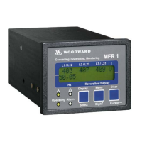
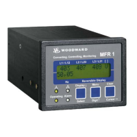
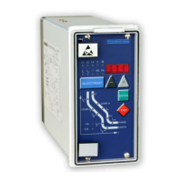
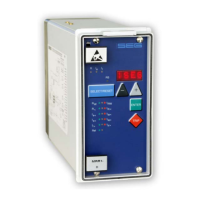
Overview of the MFR 3's design and purpose.
Details on the control unit's measurement capabilities.
Overview of features and options available based on the unit model.
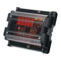
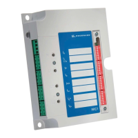
Detailed electrical wiring diagrams for MFR 3 units.
Configuration and connection details for voltage and current measuring inputs.
Configuration and connection details for discrete control and alarm inputs.
Configuration and connection details for analog inputs.
Details on control outputs and relay manager configurations.
Information on three-position and multi-functional controller outputs.
Details on interface wiring, CAN bus, and direct configuration.
Details on idle control, synchronization, dead bus start, and mains parallel operation.
Description of the operating sequences for MCB and GCB activation.
Explanation of analog PID controller operation and step response.
Description of how load and reactive power sharing is managed.
Information on alarm classes, detected alarms, and acknowledgement.
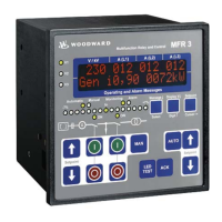
Overview of the function of each LED and push-button on the unit's front panel.
Manual control operations for GCB and MCB.
Description of values displayed on the first line in automatic mode.
Description of alarm messages displayed on the second line in automatic mode.
Parameters for language management, version, and unit numbering.
Details on the unit's three-level code and configuration hierarchy.
Procedures and requirements for configuring the unit directly via PC.
Configuration settings for various controllers (power, frequency, voltage, power factor).
Data format for transmitting information via CAN bus.
Details on the CAN bus communication protocol and message structure.
Procedure and required information for returning equipment for repair.