Installation and Connection
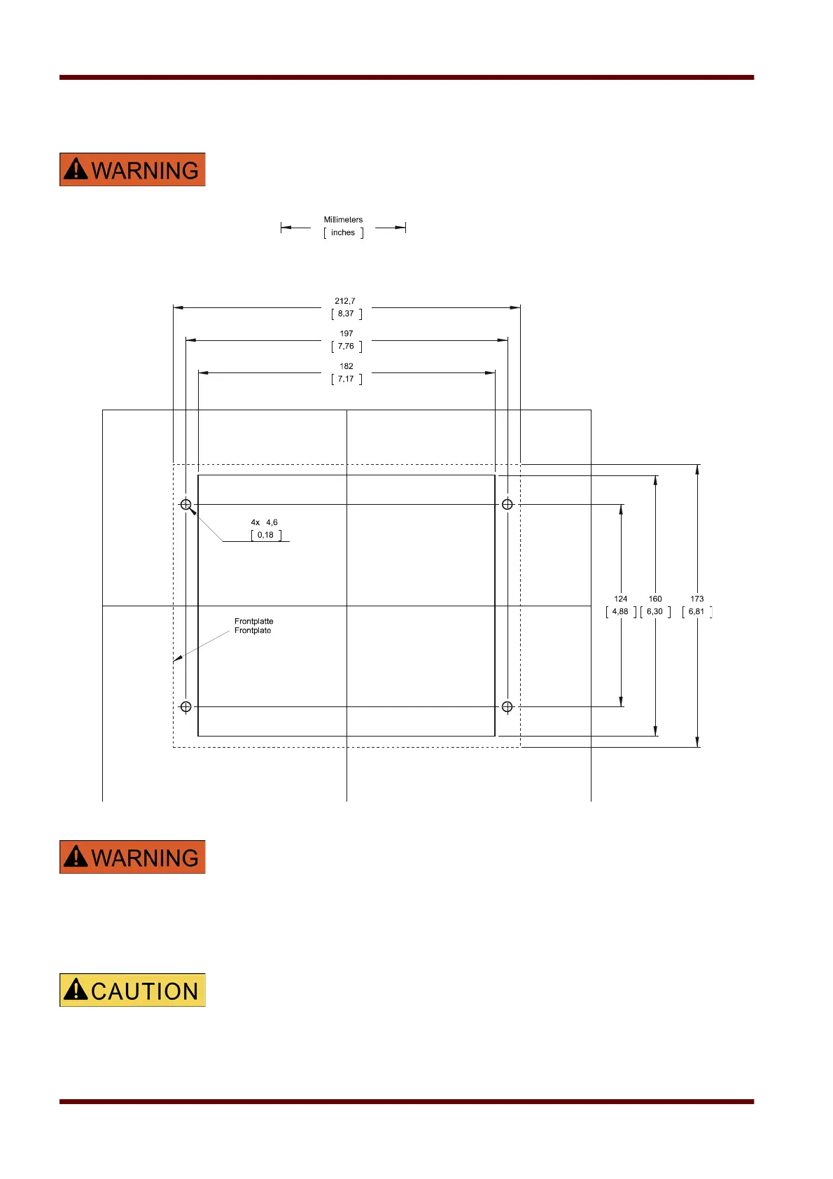
Installation Diagram
Even when the auxiliary voltage is switched-off, unsafe voltages might
remain at the device connections.
B2 Housing Door Cut-out
The housing must be carefully earthed. Connect a ground cable (4 to 6 mm
2
(AWG 12-10) / 1.7 Nm (15 lb-in)) to the housing, using the screw, which is
marked with the ground symbol (at the rear side of the device).
The power supply card needs a separate ground connection (2.5 mm
2
(AWG 14) at terminal X1 (0.55 Nm/4.9 lb-in).
Be careful. Do not overtighten the mountings nuts of the relay
(M4 metric 4 mm). Check the torque by means of a torque wrench (1.7 Nm /
15 lb-in). Overtightening the mounting nuts could due to personal injury or
damage the relay.
Page 24 EN MRA4 04/09

 Loading...