22
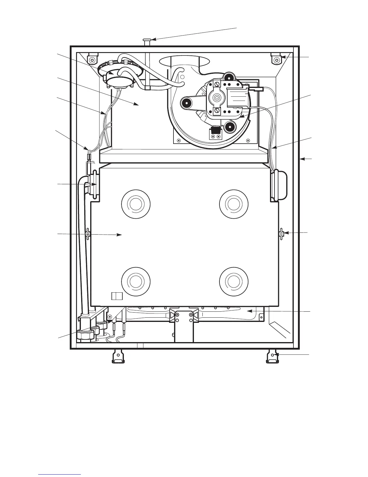
Fig. 44. Inner case components
1. Flue hood
2. Primary sensor
3. Heat exchanger
4. Combustion chamber assembly
5. Spark electrode assembly
6. Inner case cover fixing (bottom)
7. Burner assembly
8. Combustion chamber fixing screw
3
1
4
5
8
2
6
7
9
10
11
9. Inner case
10. Fan assembly
11. Inner case cover fixing (top)
12. Air pressure switch
13. Combustion sensing point
14. Fan harness
15. Main wiring harness
12
15
13
14