EasyManua.ls Logo

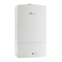
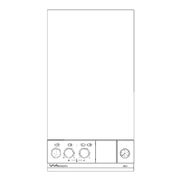
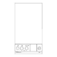
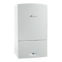
Worcester 24I RSF

Worcester 24I RSF
36 pages
To Next Page IconTo Next Page
Loading...
Supplied By www.heating spares.co Tel. 0161 620 6677
24i RSF
WALL MOUNTED COMBINATION BOILER FOR CENTRAL HEATING
AND MAINS FED DOMESTIC HOT WATER
INSTALLATION AND
SERVICING INSTRUCTIONS
GC NUMBERS
N.G. 47 311 37 L.P.G. 47 311 38
BOILER OUTPUT
To Domestic Hot Water – Modulated Control
Minimum 7.5 kW (25,600 Btu/h)
Maximum 23.4 kW (80,000 Btu/h)
To Central Heating – Modulated Control\
Auto Range Rated
Minimum 7.5 kW (25,600 Btu/h)
Maximum 23.4 kW (80,000 Btu/h)
THESE INSTRUCTIONS APPLY IN THE UK ONLY
THESE INSTRUCTIONS ARE TO BE LEFT WITH THE USER OR AT THE GAS METER
This appliance must be installed by a competent person in accordance
with the Gas Safety (Installation and Use) Regulations 1998
Question and Answer IconNeed help?

Do you have a question about the Worcester 24I RSF and is the answer not in the manual?

Worcester 24I RSF Specifications

General IconGeneral
Model24I RSF
CategoryBoiler
Output24 kW
Fuel TypeNatural Gas
MountingWall-mounted
Warranty2 years
TypeRegular
Hot Water Flow Rate11 L/min

Summary

Installation Requirements

1.1 Gas Safety Regulations

Specifies installation by a competent person as per regulations.

General Information

Benchmark Initiative Explained

Explains the Benchmark initiative for boiler installation, commissioning, and servicing.

2.13 Safety Considerations

Lists crucial safety precautions for operation and maintenance.

Open Vent System

Unsuitability for Open Vent Systems

Clear statement that the appliance is unsuitable for open vent systems.

Electrical

10.11 Electrical Safety Checks

Electrical safety checks required after installation or fault.

Commissioning The Appliance

Commissioning The Appliance (Continued)

12.4 Appliance Operation Tests

Detailed steps for testing domestic hot water and central heating modes.

Inspection And Service

14.1 Servicing Frequency and Importance

Importance and frequency of servicing.

Inspection And Service (Continued)

14.3 Appliance Dismantling for Service

Steps for dismantling the appliance to access components for service.

Replacement Of Parts

15.1 Important Safety Note for Replacement

Safety note to switch off supplies before replacing parts.

Operational Flow Diagrams

1. Central Heating Mode Sequence

Flowchart detailing the central heating operational sequence.

Operational Flow Diagrams (Continued)

2. Domestic Hot Water Mode Sequence

Flowchart detailing the domestic hot water operational sequence.

Fault Finding

A Central Heating Fault Diagnosis

Diagnostic flowchart for central heating faults.

B Domestic Hot Water Fault Diagnosis

Diagnostic flowchart for domestic hot water faults.

Fault Finding (Continued)

E Overheat Thermostat Check

Procedure for checking and resetting the overheat thermostat.

Modulating Valve Check

Diagnostic steps for the modulating valve.

Fault Finding (Continued)

K Ignition Check Procedure

Diagnostic steps for ignition problems.

Fault Finding (Continued)

L Air Pressure Switch Check

Diagnostic steps for the air pressure switch.

M Gas Valve Check

Diagnostic steps for the gas valve.

Related product manuals