Do you have a question about the Worcester 28i RSF and is the answer not in the manual?
Overview of the boiler's output and hot water flow rate.
Details of the required electrical supply and fuse ratings.
Requirements for the gas supply pressure and connection.
Guidelines for appliance placement and compartment installation.
Information about the flue system and available kits.
Details on temperature control and programmer connections.
Requirements for the heating system, including flushing and valves.
Guidance on selecting and using water fixtures with the appliance.
Important safety precautions for operating and maintaining the boiler.
Explanation of how the boiler functions in different modes.
Details of the mains voltage, wattage, and fuse ratings.
Procedures for checking the electrical system after installation or fault.
Initial checks, unpacking, site preparation, and marking for installation.
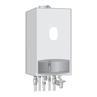
Mounting the boiler and connecting gas and water pipework.
Procedures for installing the flue system, including ducts, bends, and adapters.
Final checks, connections, and securing the appliance.
Steps to access and prepare the appliance for commissioning.
Adjusting expansion vessel and setting system pressure.
Testing controls, burner operation, and system response in various modes.
Final checks, combined operation testing, and user setup.
Explaining appliance operation and what to do if not used in frosty weather.
Emphasizing regular servicing and setting system controls.
Completing and handing over the Benchmark Log-Book.
Importance and frequency of regular appliance servicing.
Checks before servicing, including flue, ventilation, and system joints.
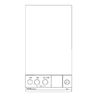
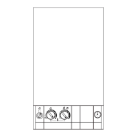
Procedures for removing appliance panels to access internal components.
Cleaning and inspecting key components like the fan, burner, and heat exchanger.
Post-service checks for gas soundness and correct operation.
Steps for accessing components and draining the system.
Detailed instructions for replacing specific parts like valves, sensors, and pumps.
Flow diagram for central heating operation and startup sequence.
Flow diagram for domestic hot water operation.
Flow diagram illustrating the frost protection function.
Flow diagram for the pump's overrun operation after heating.
Flow diagram for the general overrun function.
Flow diagram for burner pressure control in central heating.
Initial electrical system checks before detailed fault diagnosis.
Step-by-step guides for diagnosing faults based on symptoms and LED indicators.
| Model | 28i RSF |
|---|---|
| Output | 28kW |
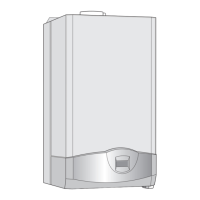
| Mounting | Wall-mounted |
| DHW Output | 28kW |
| ERP Rating | A |
| Fuel Type | Natural Gas |
| Water Pressure | 3 bar |