29
F1 2A
F2 1AT
Optional links
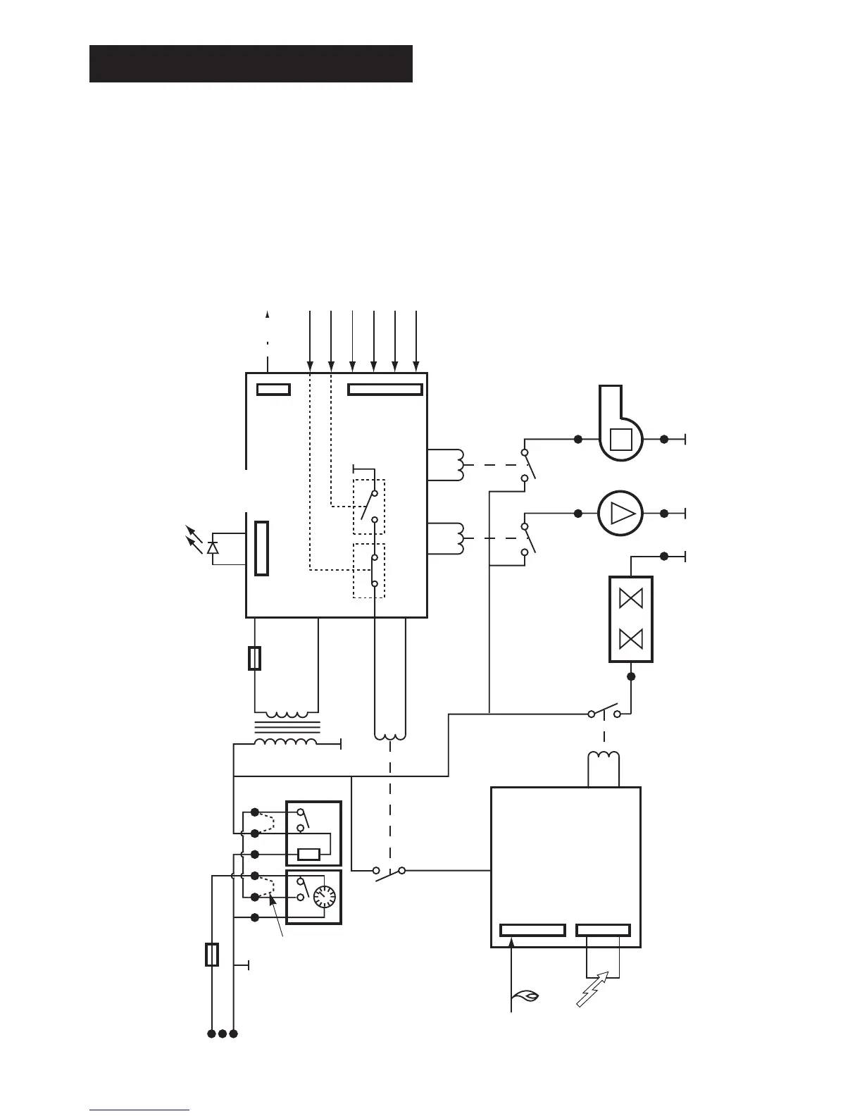
Spark
Flame sense
Outputs Inputs
Mains
indicator
Modulating
valve
Overheat stat
X6 Pins 8 & 9
X6 Pins 15 & 16
X6 Pins 5,6 & 7
X6 Pins 14, 17 & 18
X6 Pins 19 & 20
X6 Pins 3 & 4
Flow signal
CH temp. sensor
DHW temp. sensor
CH control POT
Air pressure switch
MAINS
PROGRAMMER/CLOCK
FULL SEQUENCE
CONTROLLER
GAS VALVE
LOW VOLTAGE
ELECTRONICS
(Microcontroller)
ROOM STAT
X1
X2
321
1
2
3
4
6
5
RL1
X3 Pin 1 X3 Pin 2
X4 Pin 3
X5 Pin 3
X5 Pin 1
X4 Pin 1
FAN
PUMP
RL3
RL4
N
N
N
N
L
18. Fault Finding
Note: This fault-finding information is for guidance only. Worcester Heat Systems cannot be held responsible for costs incurred by
persons not deemed to be competent.
PRELIMINARY CHECKS
Preliminary electrical system checks are the first electrical checks to be carried out during a fault-finding procedure. On completion of
the Service/Fault-Finding task which has required the breaking and remaking of electrical connections, check (a) EARTH CONTINUITY,
(b) SHORT CIRCUIT CHECK, (c) POLARITY and (d) RESISTANCE TO EARTH.