Do you have a question about the Worcester 28Si and is the answer not in the manual?
Details the electrical requirements, voltage, and fuse ratings for the appliance.
Outlines gas supply requirements, pressure, and flow rates for the appliance.
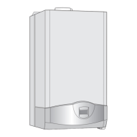
Specifies installation requirements, clearances, and suitability for different environments.
Describes flue options, positioning, and connection requirements.
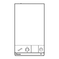
Outlines crucial safety precautions and built-in safety features of the appliance.
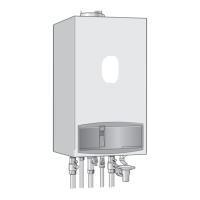
Steps for lifting, positioning, and securing the boiler onto the manifold.
Guidance on measuring, cutting, and assembling flue ducts for various lengths.
Details fitting the flue assembly when terminal access is available.
Details checks for wall suitability, flatness, and weight support.
Instructions for preparing and fitting flue components, including restrictor rings.
Instructions for fitting the flue assembly when terminal access is not available.
Final checks and steps to complete the appliance installation.
Describes marking and drilling for wall mounting and flue connections.
Instructions for fitting the wall mounting plate and manifold assembly.
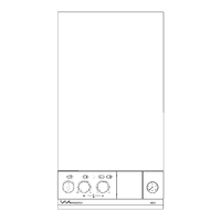
Procedure for checking and adjusting burner pressure.
Instructions for setting the expansion vessel charge pressure.
Details on filling and pressurizing the system to the correct pressure.
Final steps including pressure gauge removal and gas soundness test.
Post-replacement checks for gas soundness and functional verification.
Steps for replacing the gas valve, including setting and pressure checks.
Steps for removing and replacing the pressure gauge.
Instructions for removing and replacing the spark electrode assembly.
Instructions for removing and replacing the relief valve.
Procedures for draining the primary system and DHW circuit before replacement.
Procedure for replacing the flame sense electrode.
Steps for replacing the main control board, including transformer transfer.
General advice for component replacement, including seals and wiring.
Steps for removing and replacing the burner assembly.
Troubleshooting steps for burner lockout issues, checking gas, electrodes, and sensors.
Troubleshooting steps for sensor faults, checking DHW and CH sensors and wiring.
Troubleshooting steps for air pressure faults, checking fan, switch, and flue.
Refers to other instructions for boiler fitting and system flushing.
| Model | 28Si |
|---|---|
| Output | 28kW |
| Efficiency Rating | A |
| ErP Rating | A |
| Flow Rate | 11.4 l/min |
| Water Pressure | 3 bar |
| Max Gas Rate | 2.8 m3/h |