The appliance may be installed in any room but refer to the
requirements of the current IEE Regulations and, in Scotland, the
relevant electrical provisions of the Building Regulations with
respect to the installation of appliances in rooms containing
baths or showers.
Where a room sealed appliance is installed in a room containing
a bath or shower, any switch or appliance control using mains
electricity must NOT be able to be touched by a person using the
bath or shower.
The appliance is NOT suitable for external installation.
No special wall protection is required.
The wall must be able to support the weight of the appliance.
Refer to Table 4.
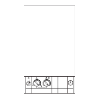
The specified clearances must be available for installation and
servicing. Refer to Table 8, Fig.3, 4 and Section 6. Air Supply.
The appliance can be installed in a cupboard/compartment to
be used for airing clothes providing that the requirements of
BS6798 and BS5440 Part 2 are followed. Refer to Section 2.4.
The airing space must be separated from the boiler space by a
perforated non-combustible partition. Expanded metal or rigid
wire mesh is acceptable provided that the major dimension is
less than 13mm.
The clearance between the front of the appliance and the
cupboard/compartment door should be not less than 75mm.
LPG Installation. Refer to Section 1.9.
4. Siting The Appliance
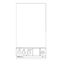
Fig.4. Appliance casing dimensions and
required clearances (side view).
All dimensions in mm
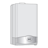
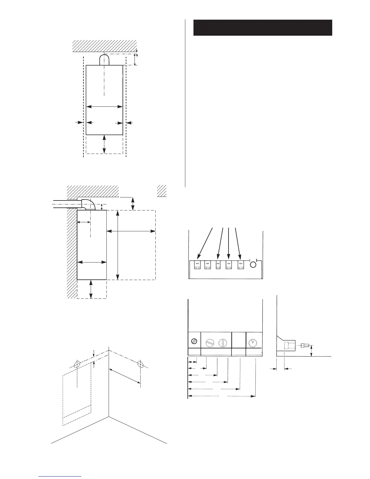
Fig. 5. Side flue opening
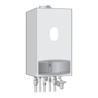
A CH Flow = 55
B DHW Flow = 120
C Gas = 185
D Cold Water Inlet = 250
E CH Return = 315
F Relief Valve Discharge = 375
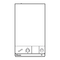
Fig. 3. Appliance casing dimensions and
required clearances (front view).
All dimensions in mm
30
170
10
10
6
A
B
C
D
E
190
(A, B, C, D,)
20
A B C D E
View on underside of appliance showing
connections
Valves shown closed.
Fig. 6. Pipework connections
All dimensions in mm
440
106
600
800
230
200
360
200
230
200
F
All dimensions in mm
NOTE:
Casing is
3mm above
the top of the
wall mounting
frame. Refer to
Fig.15.
106
F