17
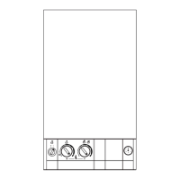
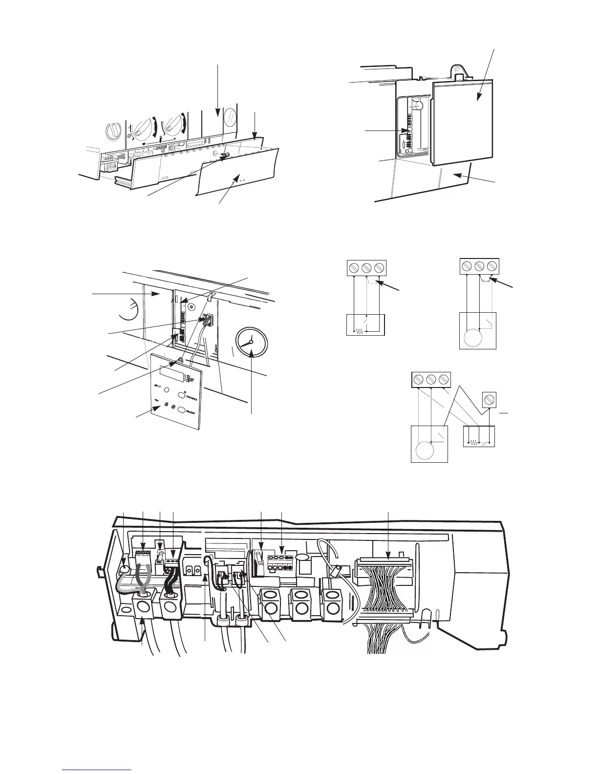
Fig.29. Facia connections cover
Facia
Controls
connections
cover
Fixing screw
Facia bottom panel
(clip-on)
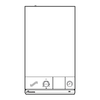
Fig.30. Programmer cover
Cover panel
Facia
Programmer
connections
Fig.33. Facia connections
1 2
3
4 5
6
7
8
9
10
1. Earth screw
2. Mains connection (L N)
3. Fuse F1
4. Mains voltage room thermostat/external control-mains
voltage ST8
5. Fuse F2
6. Controls 24V - ST13
7. Mains harness ST16
8. Fan ST1
9. Pump ST5
10. Earth tag
11. Cable clamps (threaded)
11
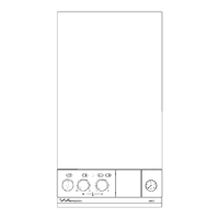
Fig.31. Programmer connection
Facia
Programmer
connector
Programmer
connections
Clip
Programmer
Pressure gauge
Control
board
Fig 32 - Mains Voltage External Controls Connections
230 V Room Thermostat Connections
Ns
Ls
L
R
ST8
Ns
Ls
LR
ST8
Remove Link
Neutral
Live
Switched Live
Neutral
Live
Switched Live
Motor
230 V Programmer Connections
230 V room thermostat and
Programmer Connections
Ns
Ls
L
R
ST8
Neutral
Live
Neutral
Live
Switched Live
Motor
Switched Live
Series
connection
to be made
safe
NOTE: Only double insulated controls not requiring an earth can be used
Remove Link