To set the burner pressure. See Fig. 40.
The minimum and maximum burner pressures must be set after
a new gas control has been fitted.
The maximum burner pressure must be set first, as any
adjustment of the maximum pressure influences the minimum
pressure setting.
Start the appliance in the domestic hot water mode as described
in section 13.6. - Appliance Operation.
Adjust the maximum pressure adjustment (2mm Allen screw on
the gas valve) to give a burner pressure of 13.5 mbar on natural
gas. End the demand and reset the appliance by interrupting the
mains electricity supply. (Otherwise there is a four minute anti-
cycle delay at the end of a demand).
Open a hot tap.
Remove one of the blue leads from the modulating solenoid on
the gas valve to ensure that the burner pressure remains at the
minimum setting. See Fig. 40.
Adjust the minimum pressure to 1 mbar using a 3mm Allen key.
Replace the blue lead and re-check the pressures.
After completing the adjustments, check the minimum and
maximum pressures and re-adjust as necessary.
Re-fit the adjuster sealing cap and coat with a small amount
of paint to seal the cap to make any subsequent adjustment
obvious.
12. Central Heating Sensor.
See Fig. 41.
Check that the electricity supply to the appliance is turned off.
Hinge the facia assembly in the servicing position as described in
Section 15.3(c and d).
Carefully pull off the two leads from the sensor.
Pull off the sensor and spring retaining clip from the pipe.
Fit the replacement sensor in reverse order with a layer of heat
sink compound between the faces. Refit the leads.
13. Domestic Hot Water Sensor. See Fig. 41.
Check that the electricity supply to the appliance is turned off.
Hinge the facia assembly in the servicing position as described in
Section 15.3(c and d).
Carefully pull off the two leads from the sensor.
Undo and remove the clamping screw.
Pull off the sensor and spring retaining clip from the pipe.
Fit the replacement sensor in the reverse order ensuring a layer
of heat sink compound is between the faces. Refit the leads.
14. Circulating Pump. See Fig. 41.
Check that the electricity supply to the appliance is turned off.
Drain the central heating circuit as described in Section 16.3(a).
Hinge the facia assembly in the servicing position as described in
Section 15.3(c).
Remove the burner assembly as described in Section 15.3(h).
Undo the two union nuts and the pipe to the expansion vessel,
remove the pump from the pipe-work. Support the pump and
remove the electrical cover.
Disconnect the electrical wires taking note of their positions.
Fit the replacement pump in the reverse order using new sealing
washers.
(Alternatively replace the pump head only by removing the four
Allen screws on the pump, remove the head and support whilst
removing the electrical connections. Refit the new head).
Open the valves and fill and re-pressurise the system as
described in Section 13.2
Note: The direction of flow should be upwards. The speed should
always be set to maximum.
15. Expansion Vessel.
Drain the central heating circuit as described in Section 16.3(a).
Isolate the gas supply at the mains.
Then either fit a separate expansion vessel on the central heating
return to the appliance or replace the existing vessel as
described below.
Drain the domestic circuit as described in Section 16.3(b).
Disconnect the flue system at the boiler.
Disconnect the appliance pipework at the appliance entry points
ensuring precautions are taken to cope with any water
remaining in the appliance.
Remove the appliance from the wall.
Disconnect the expansion vessel from the appliance by undoing
the fitting nut at it’s base.
Fit the replacement vessel in the reverse order.
Open the valves and fill and re-pressurise the system as
described in Section 13.3
16. Pressure Relief Valve. See Fig. 41 and 42.
Drain the central heating circuit as described in Section 16.3(a).
Hinge down the facia assembly as described in Section 15.3(c).
Remove the Bottom panel as described in Section 15..3(d).
Undo the discharge pipe connection and remove the valve
retaining clip. Remove the valve taking care not to distort the
pipework.
Fit the replacement valve in reverse order. Reconnect the
discharge pipe.
Open the valves and fill and re-pressurise the system as
described in Section 13.3.
17. Water Flow Turbine. See Fig. 41 and 43.
Check that the electricity supply to the appliance is turned off.
Drain the domestic hot water circuit as described in Section
16.3(b).
Remove the two upper screws and hinge down the facia panel as
described in Section 15.3(c).
Disconnect the electrical connection.
Unscrew the securing nuts and remove the turbine housing from
the pipework.
Fit the replacement water flow turbine in the reverse order
ensuring new fibre washers are fitted to the new turbine body.
Check that the correct, blue, flow restrictor is fitted.
NOTE: Washers are different
Inlet
= Outlet =
24
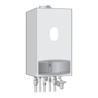
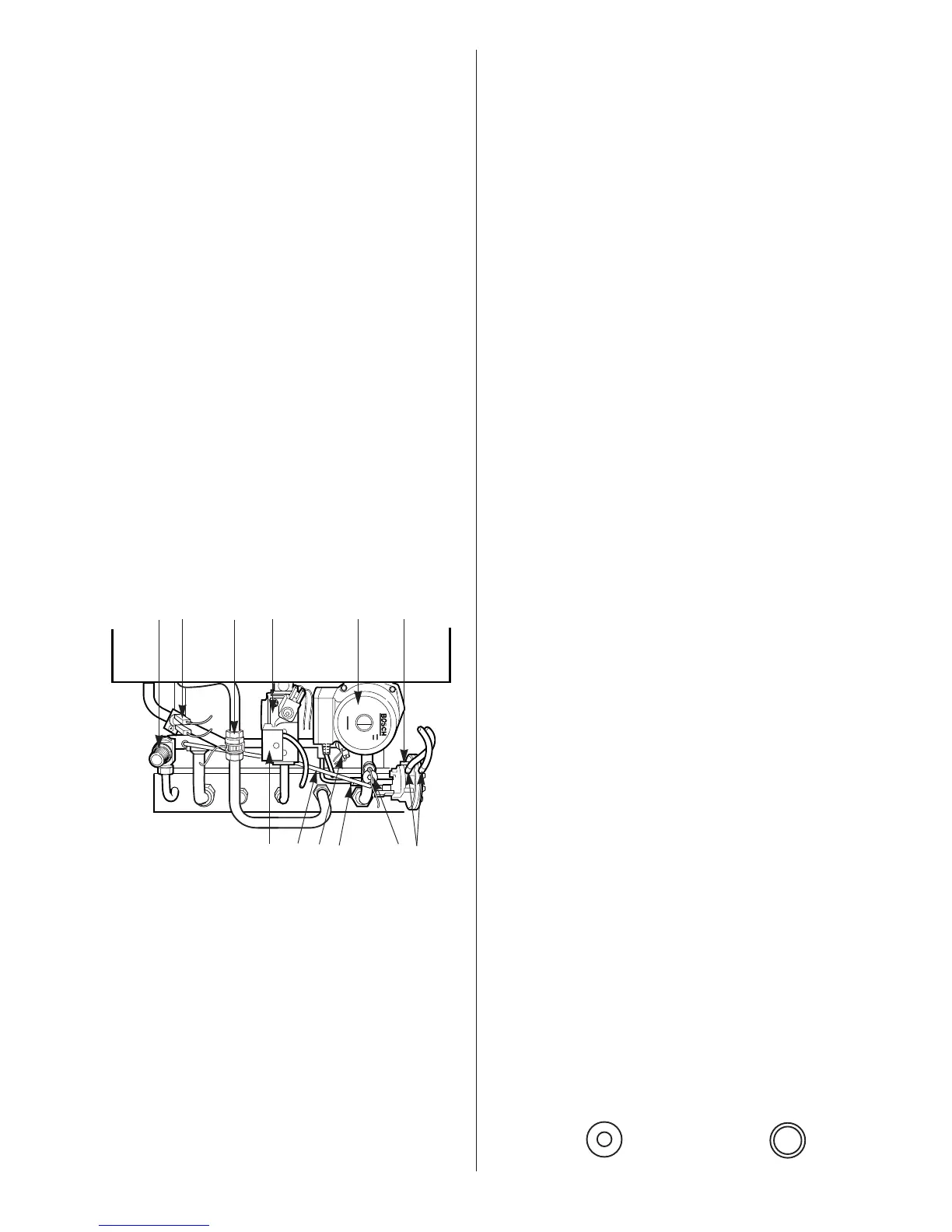
Fig. 41. Appliance Components
(Lower Assembly)
1 Pressure relief valve
2 Domestic hot water sensor
3 Water flow turbine
4 Gas valve
5 Pump
6 Air pressure switch
7 Air pressure switch connecting tubes
8 Pressure gauge connection
9 Gas valve electrical connections
10 By-pass pipe
11 Fixing disc and screw
12 Central heating sensor
4 5 61 2 3
98 71110
12