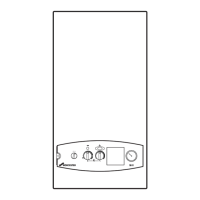
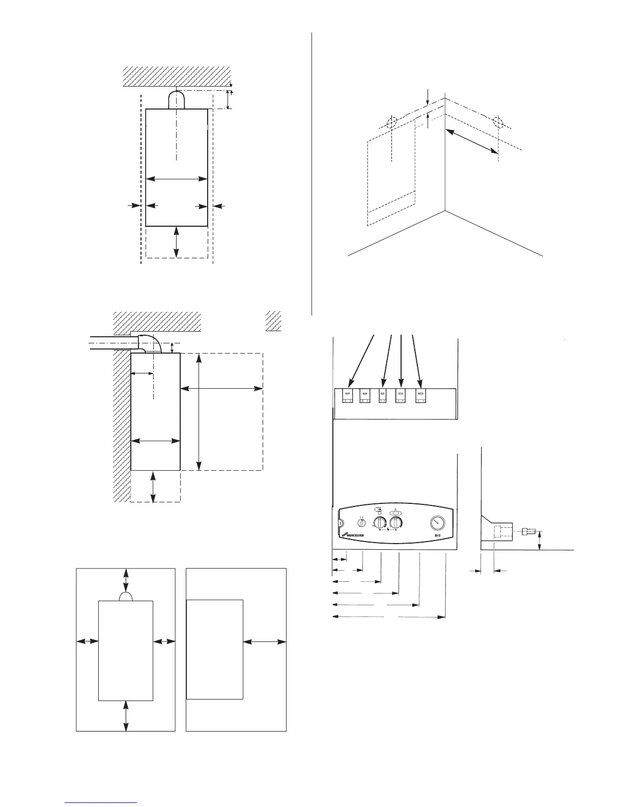
Fig. 4. Appliance casing dimensions and
required clearances (side view).
All dimensions in mm
Fig. 6. Side flue opening
24Si II 28Si II
A CH Flow = 55 75
B DHW Flow = 120 140
C Gas = 185 205
D Cold Water Inlet = 250 270
E CH Return = 315 335
F Relief Valve Discharge = 375 395
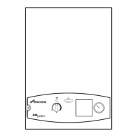
Fig. 3. Appliance casing dimensions and
required clearances for installation/servicing
All dimensions in mm
30
150
10
10
6
B
C
D
E
190
(A, B, C, D,)
20
A B C D E
F
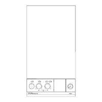
View of underside of appliance showing
connections
Valves shown closed.
Fig. 7. Pipework connections
All dimensions in mm
24Si II = 400
114
600
740
230
360
200
200
F
All dimensions in mm
114
28Si II = 440
Fig. 5. Unventilated compartment clearances
230
200mm
150mm from
the top of the
flue elbow
80mm
80mm
240mm
From a
removable
panel
eg. door
A