See Figs. 8, 9, 10, 11, 12 and 13.
10.1 MAINS SUPPLY.
230 V ~, 50 Hz, 180 watts.
External Fuse: 3A. Internal Fuses: T 2A (F1), and T 1.25A (F2).
Spare internal fuses are supplied at the rear of the facia, next to
the pressure gauge.
10.2 It must be possible to completely isolate the appliance.
10.3 The following connection alternatives must be used:
A 3 amp fused three-pin plug and unswitched shuttered socket
outlet (both complying with the requirements of BS 1363) or a
double pole isolator with a contact separation of 3mm in all
poles and supplying the appliance and controls only.
10.4 The appliance must be earthed.
10.5 Mains Cable. 0.75mm
2
(24 x 0.20mm) to BS 6500 Table 16.
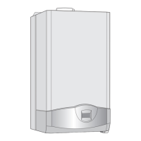
The mains cable must be connected into the terminal
ST12,
marked L (Brown or Red lead),
N (Blue or Black lead) and the
earth stud and be held securely in the cable clamp. For access
undo the three bottom screws and remove the facia access cover.
See Fig. 23.
10.6 The wiring between the appliance and the electrical supply
shall comply with current IEE Wiring Regulations and any local
regulations which apply.
10.7 If a room thermostat and/or external programmer is to be
fitted refer to Figs 11, 12 and 13. The devices must be suitable for
use with mains voltage.
10.8 Facia mounted programmers are available as optional
extras. Instructions are supplied with the programmer kits.
10.9 A time switch or programmer can be fitted externally to the
appliance.
10.10 The boiler is fitted with an internal frost thermostat which
will protect the boiler from frost damage, as long as the mains
switch on the boiler is in the on position. However, if frost
protection is necessary for the system, please contact Worcester
Heat Systems Technical Helpline. Tel: 0990 266241.
10.11 SAFETY CHECK.
After installation or in the event of an electrical fault the
electrical system shall be checked for short circuits, fuse failure,
incorrect polarity of connections, earth continuity and resistance
to earth.
10. Electrical
9
Fig. 8. Mains electricity connections.
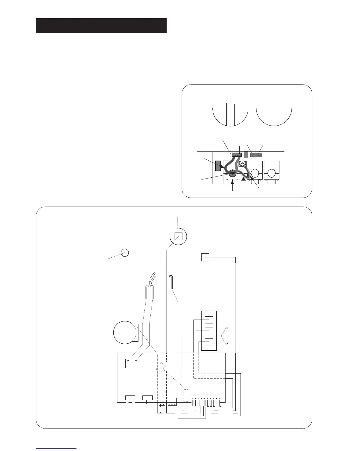
Fig. 9. Wiring diagram.
Strain relief clamp
Green/yellow
Brown
Brown
Blue
Green/yellow
Blue
Fan
Overheat
cut-off
device
Flame sense
electrode
Fan electrical connections
Black 1
White 4
Red 3
Air pressure
switch
Spark
electrode
Spark
transformer
Mains in
Link
Control Board
DHW
sensor
Flow
switch
ST16
2 blue
2 orange
2 brown
white
red
black
brown
blue
blue
brown
2 violet
white
2 red
2 yellow
2
pink
ST12 ST8
ST15 ST1
Pump
CH sensor
Gas valve
Reg
Main
2
3
1
Main
L
230V
ST12
N
Ns
LR
LS
2 green