Remove
the
leads from
the
hot
water sensor
and
hot
water ther-
mostat.
Unscrew
the
flow switch
head
and
carefully lay to
one
side. It
is
not
necessary to unplug
the
switch.
Undo
the
outlet union connection
at
the
heat
exc
han
ger. Release
the locking screw
at
the
heat
exchanger a
nd
the union connections
at
th
e mounting manifold.
Lay
the inlet
and
outlet assemblies to
one
side.
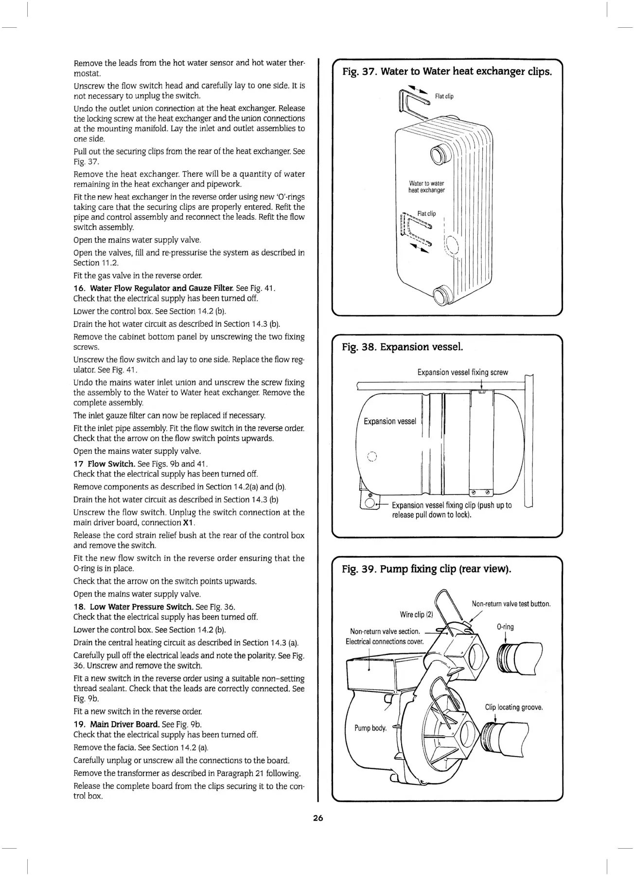
Pull
out
the
securing clips from
the
rear of the heat exchanger. See
Fig.
37.
Remove
the
heat
exchanger
. There will
be
a
quant
ity of
water
remaining in
the
heat exchanger
and
pipework.
Fit
the
new heat exchanger in the reverse order using new '0'-rings
taking care
that
the sec
ur
ing clips are properly entered.
Refit
the
pipe
and
control assembly
and
reconnect
the
leads.
Refit
the flow
switch assembly.
Open
the
mains water supply valve.
Open
the
valves,
fill
and
re-pressurise the system
as
described in
Section
11
.2.
Fit
the
gas valve in
the
reverse order.
16
. Water Flow Regulator and Gauze Filter. See
Fig
.
41
.
Check
that
the
electrical supply
has
been
tu
rn
ed
off.
Lo
wer
the
control box. See Section 14.2
(b).
Drain
the
hot
water circuit
as
described in Section 14.3
(b).
Remove the cabinet
bottom
panel by unscrewing
the
two fixing
screws.
Unscrew the
flow
switch and lay to one sid
e.
Replace
the
fl
ow reg-
ulator. See
Fig
.
41
.
Undo
the
mains water inlet union
and
unscrew
the
screw fixing
the
assembly to the Water to Water heat exchanger. Remove
the
complete assembly.
The inlet gauze filter
can
now
be
replaced
if
necessary.
Fit
th
e inlet pipe assembly.
Fit
the
fl
ow
switch in the reverse order.
Check
that
th
e arrow
on
the flow switch points upwards.
Open
the
mains water
supp
ly valve.
1 7 Flow Switch. See Figs.
9b
and
41.
Check
that
the electrical supply has been turned o
ff.
Remove
com
ponents
as
described
in
Section
14
.
2(a)
and
(b
).
Drain
the
hot
water circuit
as
described in Section 14.3
(b)
Un
screw
the
flow switch. Unplug
the
switch connection
at
the
main driver board, connection
X1
.
Release
the
cord strain relief
bush
at
the
rear of
the
control box
and
remove
the
switch.
Fit
the
new
flow switch in
the
reverse
order
ensuring
tha
t
the
0-ring is in place.
Check
that
the arrow
on
the
switch points upwards.
Open the mains water supply valve.
18.
Low
Water Pressure Switch. See
Fig
. 36.
Check
that
the
electrical supply
has
been turned
off.
Lower
the
control box. See Section 14.2
(b)
.
Drain the central heating circuit
as
described in Section 14.3
(a).
Carefully pull off the electrical leads
and
note the polarity. See
Fig
.
36. Unscrew
and
remove
the
switch.
Fit
a new switch in the reverse order using a suitable non- setting
thread sealant.
Check
that
the
leads are correctly connected. See
Fig
. 9b.
Fit
a new switch in
the
reverse order.
19
.
Main
Driver Board. See
Fi
g. 9b.
Check
that
the electrical supply
has
been turned off.
Remove
th
e facia. See Section 14.2
(a)
.
Carefully unplug or
un
screw all the connections
to
the board.
Remove
the
transformer
as
described in Paragraph
21
follo
wing.
Release the complete board from
the
clips securing it to the con-
trol box.
26
Fig.
37.
Water
to
Water
heat exchanger clips.
W
ater
to
wa
ter
heat
ex
ch
a
ng
er
I
I
I
I~,
,r
'
',\
I
..
_
.....
.
......
Fig
. 38. Expansion vessel.
Expan
s
ion
vessel
fix
i
ng
screw
Expans
i
on
vesse
l
Expansion
vessel
fixing
cl
ip
(
pus
h
up
to
re
lea
se
pu
ll
dow
n
to
lo
ck)
.
Fig.
39.
Pump
fixing
clip
(rear
view).
Non-retu
rn
va
l
ve
te
st
butto
n.
Non
-return
valve
section.