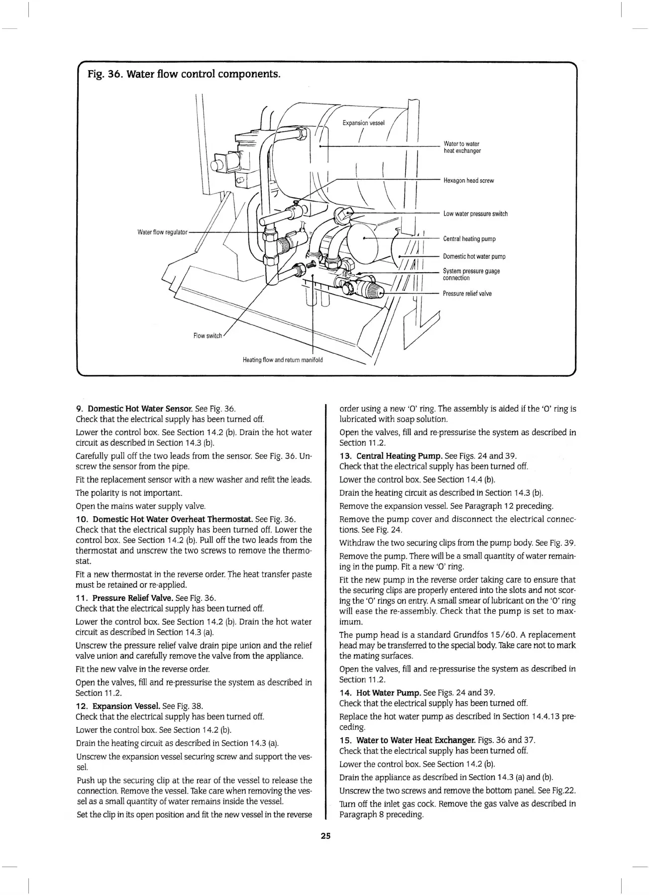
Fig.
36.
Water
flow control components.
Fl
ow
swit
ch
.,r--------
Low
wa
t
er
p
ressure
swit
ch
..-4.
\\
V'
..........-
...,:.....:....,;;....;__
Domes
tic
ho
t
water
pu
mp
.---,------,--:-'-c,....,..,-..,--
System
pre
ssure
guag
e
c
on
nect
io
n
H
eating
flow
a
nd
return
man
i
fo
ld
9. Domestic
Hot
Water Sensor. See
Fig.
36.
Check
that
the
electrical supply
has
been turned off.
Lower
the
control box. See Section 14.2
(b)
. Drain
the
hot
water
circuit as described in Section
14
.3
(b)
.
Carefully pull off
the
two leads from
the
sensor. See
Fig
. 36. Un·
screw
the
sensor from
the
pipe.
Fit
the
replacement sensor with a new washer
and
refit
the
leads.
The polarity is
not
important.
Open
the
mains water supply valve.
10.
Domestic
Hot
Water Overheat Thermostat. See
Fig
. 36.
Check
that
the
electrical supply
has
been turned
off.
Lower
the
control box. See Section 14.2
(b)
. Pull off
the
two leads from
the
thermostat
and
unscrew
the
two screws to remove
the
thermo·
stat.
Fit
a new thermostat in
the
reverse order. The
heat
transfer
paste
must
be
retained or re-applied.
11 . Pressure Relief Valve. See
Fig
.
36
.
Check
that
the
electrical supply
has
been turned
off.
Lower
the
control box. See Section 1 4.2
(b).
Drain
the
hot
water
circuit
as
described in Section 14.3
(a).
Unscrew
the
pressure relief valve drain pipe uni
on
and
the
relief
valve union
and
carefully remove
the
valve from
the
appliance.
Fit
the
new valve
in
the
reverse order.
Open
the
valves,
fill
and
re·pressurise
the
system
as
described in
Section
11
.2.
12.
Expansion Vessel. See
Fig
. 38.
Check
that
the
electrical supply
has
been turned
off.
Lower the control box. See Section 14.2
(b).
Drain the heating circuit
as
described in Section 14.3
(a).
Unscrew the expansion vessel securing screw
and
support
the
ves·
sel.
Push up
the
securing clip
at
the
rear of
the
vessel to release
the
connection. Remove
the
vessel.
Take
care when removing
the
ves·
sel
as
a small quantity of water remains inside the vessel.
Set the
clip
in its open position
and
fit
the new vessel in
the
reverse
25
order using a new
'0'
ring. The assembly is aided
if
the
'0'
ring is
lubricated with
soap
solution.
Open
the
valves,
fill
and
re·pressurise
the
system
as
described in
Section 11.2.
13
. Central Heating Pump. See
Figs.
24
and 39.
Check
that
the
electrical supply has been turned
off.
Lower
the
control box. See Section 14.4
(b).
Drain
the
heating circuit
as
described
in
Section 14.3
(b)
.
Remove
the
expansion vessel. See Paragraph 1 2 preceding.
Remove
the
pump
cover
and
disconnect
the
electrical connec·
tions. See F
ig.
24.
Withdraw
the
two securing clips from
the
pump
body
. See
Fig
.
39
.
Remove the pump. There
will
be
a small quantity of water remain·
ing
in
the
pump.
Fit
a new '0 ' ring.
Fit
the
new
pump
in
the
reverse order taking care to ensure
that
the
securing clips are properly entered into the slots
and
not
scar·
ing the
·o·
rings on entry. A small smear oflubricant
on
the ·
o·
ring
will
ease
the
re-assembly. Check
that
the
pump
is
set
to max·
imum.
The
pump
head
is a
standard
Grundfos 1 S/ 60. A
replacement
head
may
be
transferred to the special
bod
y.
Take
care not to mark
the
mating surfaces.
Open
the
valves,
fill
and
re·pressuri
se
the
system
as
described
in
Section 11.2.
14
.
Hot
Water Pump. See
Figs.
24
and
39
.
Check
that
the
electrical supply has been turned off.
Replace
the
hot water
pump
as
descri
bed
in Section 14.4.
13
pre·
ceding.
15
. Water
to
Water Heat Exchanger.
Figs
.
36
and
37.
Check
that
the
electrical supply
has
been
turned
off.
Lower
the
control box. See Section 14.2
(b)
.
Drain
the
appliance
as
described
in
Section 14.3
(a)
and
(b).
Unscrew
the
two screws and remove the bottom panel. See
Fig
.22.
Turn
off
the
inlet gas cock. Remove
the
gas valve
as
described in
Paragraph 8 preceding.