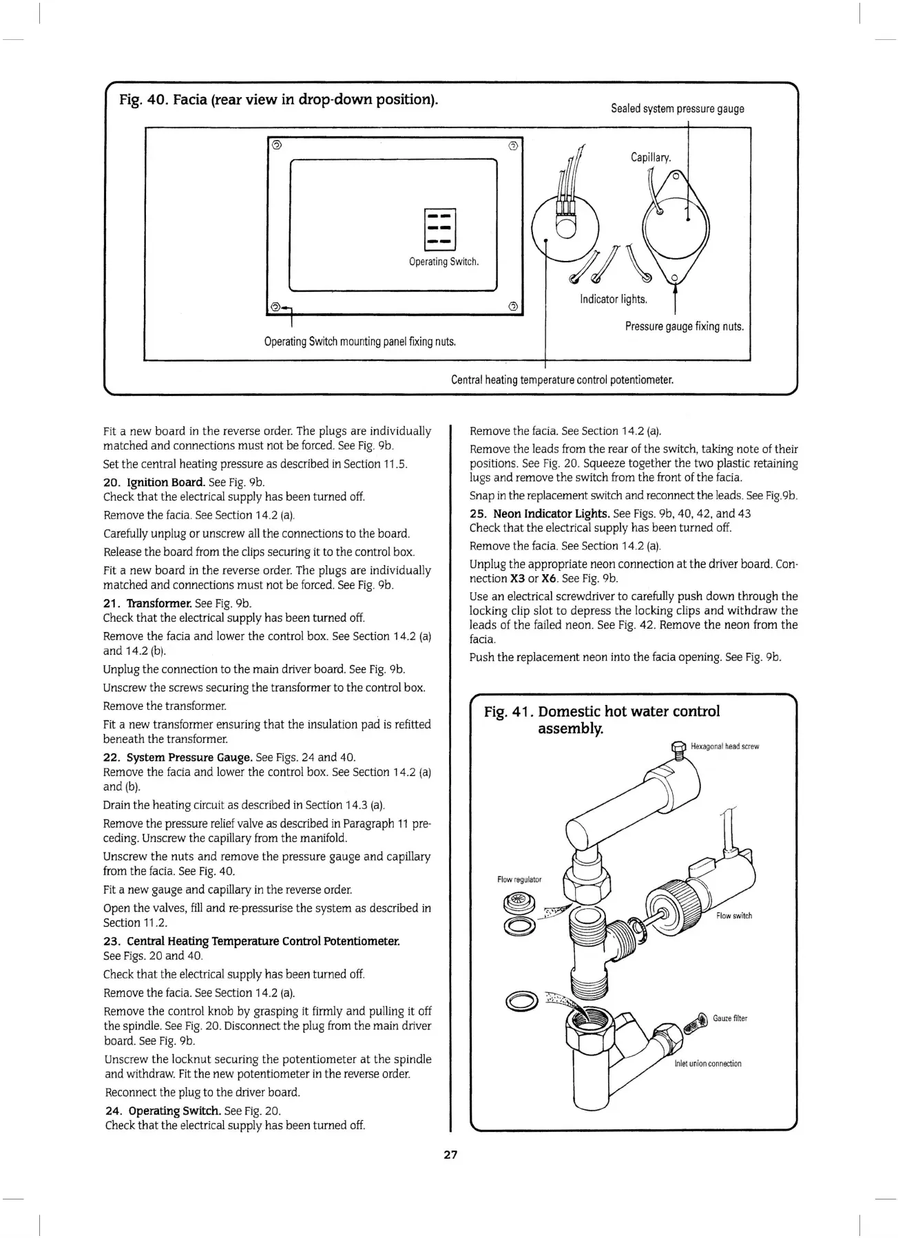
Fig.
40.
Facia (rear
view
in drop-down position).
S
ealed
system
pressure
gauge
Cap
ill
ary.
g
-
-
Operati
ng
Swit
ch.
Indicato
r
lights.
Pressure
gauge
f
ix
i
ng
nuts.
Operating
Swit
ch
mounting
panel
fixing
nuts.
Fit a
new
board
in
the
reverse order. The plugs are individually
matched
and
connections
must
not
be
forced. See
Fig
.
9b
.
Set
the
central heating pressure
as
described in Section
11
.5.
20.
Ignition Board. See
Fig
.
9b
.
Check
that
the
electrical
supp
ly
has
been
turned
off.
Remove the facia. See Section 14.2 (
a)
.
Carefully unplug or unscrew all
the
connections to the board.
Release the board from
the
clips securing it to the control box.
Fit a
new
board
in
the
reverse order. The plugs are individually
matched
and
connections
must
not
be forced. See
Fig.
9b.
21.
Transformer. See
Fig.
9b.
Check
that
the
electrical supply
has
been
turned
off.
Remove the facia and lower
the
control box. See Section 14.2
(a)
and
14.2
(b).
Unplug
the
connection
to
th
e main driver board. See
Fig
. 9b.
Unscrew
the
screws securing t
he
transformer
to th
e control
box
.
Remove the transformer.
Fit a new transformer ensuring
that
the insulation
pad
is refitted
beneath
the transformer.
22
. System Pressure Gauge. See
Figs.
24
and
40.
Remove
the
facia
and
lower
the
control box. See Section 14.2
(a)
and(b)
.
Drain
the
heating c
ir
cuit
as
described
in
Section 14.3
(a)
.
Remove the pressure relief valve
as
described in Paragraph
11
pre·
ceding. Unscrew the capillary from
the
manifold.
Unscrew
the
nuts
and
remove
the
pressure gauge
and
capillary
from
the
facia. See
Fig.
40.
Fi
t a new gauge
and
capillary in
the
reverse order.
Open
the
valves,
fill
and
re·pressurise the system as described in
Section
11
.2.
23.
Central Heating Temperature Control Potentiometer.
See Figs.
20
and
40.
Check
that
the
electrical supply
has
been
turned
off.
Remove
the
facia. See Section 14.2
(a)
.
Remove
the
control knob by grasping it firmly
and
pulling it off
the
spindle. See
Fig
. 20. Disconnect the plug from
the
main driver
board. See
Fig.
9b.
Unscrew
the
l
ocknut
securing
the
potentiometer
at
the
spindle
and
withdraw. Fit
the
new
potentiometer in
the
reverse order.
Reconnect the plug
to
the
driver board.
24.
Operating Switch. See
Fig
. 20.
Check
that
the
electrical supply
has
been
turned
off.
Cen
tral
hea
ting
tempera
tur
e
control
potent
i
ometer.
27
Remove
the
facia. See Section
14
.2 (
a).
Remove
the
leads from the rear of
th
e switch, taking note of their
po
sitions. See
Fig.
20. Squeeze together
the
tw
o plastic retaining
lugs
and
remove
the
switch from the front of the facia.
Snap
in
the
replacement switch
and
reconnect the leads. See Fig.9b.
25.
Neon Indicator Lights. See
Figs.
9b
,
40
, 42,
and
43
Check
that
the
electrical
supp
ly
has
been
turned
off.
Remove
the
facia. See Section
14
.2 (
a).
Unplug
the
appropriate neon connection
at
the
driver board.
Con
-
nect
io
n
X3
or X6. See F
ig.
9b.
Use an electrical screwdriver
to
carefu
ll
y
push
down through
the
locking clip slot
to
depress
the
locking clips
and
withdraw
the
leads
of
the
failed
neon
. See
Fig.
42. Remove t
he
neon from
the
facia.
Push
the
replacement neon
in
to
the
facia openi
ng
. See Fig. 9b.
Fig. 41 . Domestic
hot
water control
assembly.