Disconnect
the
leads from
the
programmer noting their align-
ment.
Fit
the replacement programmer
and
reconnect
the
leads check-
ing
that
they are correctly positioned.
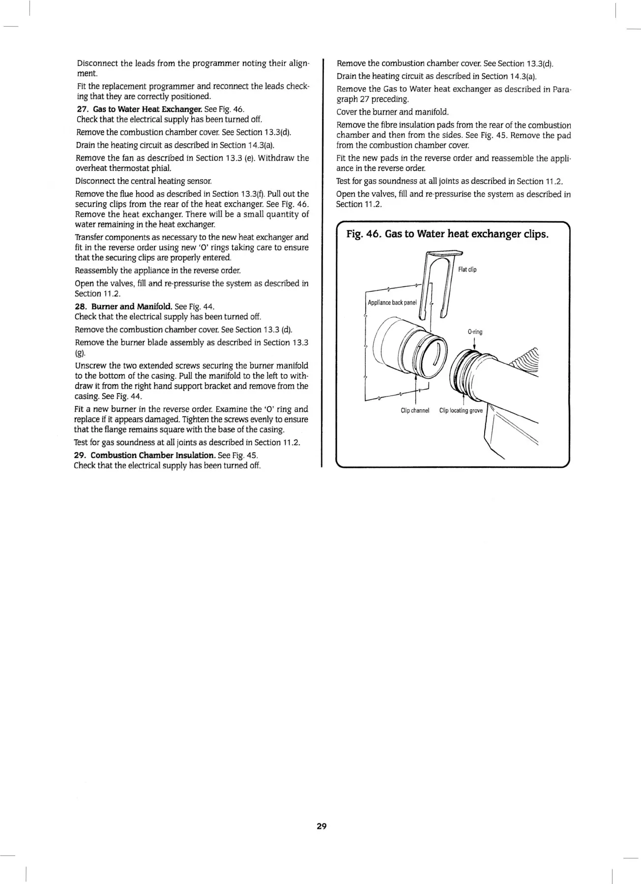
27
.
Gas
to Water
Heat
Exchanger. See
Fig
. 46.
Check
that
the electrical supply
has
been turned o
ff.
Remove
the
combustion chamber
cover.
See Section 13.
3(d).
Drain
the
heating circuit as described
in
Section 14
.3
(a).
Remove
the
fan as described in Section 13.3
(e)
. Withdraw
the
overheat thermostat phial.
Disconnect the central heating sensor.
Remove
the
flue hood
as
described in Section
13
.
3(~
.
Pull
out
the
securing clips from
the
rear
of
the
heat
exchanger. See
Fig.
46.
Remove
the
heat
exchanger. There will
be
a small
quantity
of
water remaining
in
the
heat
exchanger.
n-ansfer components as necessary to the new heat exchanger and
fit in
the
reverse order using new '
0'
rings taking care to ensure
that
the
securing clips are properly entered.
Reassembly
the
appliance
in
the reverse order.
Open
the
valves,
fill
and
re-pressurise
the
system as described in
Section 11.2.
28.
Burner
and
Manifold. See
Fig
. 44.
Check
that
the
electrical supply has been turned off.
Remove
the
combustion chamber
cover.
See Section 13.3
(d).
Remove
the
burner blade assembly as described
in
Section 13.3
(g).
Unscrew
the
two extended screws securing the burner manifold
to the bottom of the casing.
Pull
the
manifold to
the
left to with-
draw it from the right
hand
support bracket
and
remove from
the
casing. See
Fig
. 44.
Fit a
new
burner
in
the
reverse order. Examine
the
'0 ' ring
and
replace
if
it appears damaged. Tighten the screws evenly to ensure
that
the
flange remains square wi
th
the base of
the
casing.
Test
for gas soundness
at
all joints
as
described in Section 11.2.
29.
Combustion
Chamber
Insulation. See
Fig
. 45.
Check
that
the
electrical supply has been turned
off.
29
Remove
the
combustion chamber cover. See Section 13.3(d).
Drain
the
heating circuit as described
in
Section 14.3(a).
Remove
the
Gas to Water
heat
exchanger as descri
bed
in Para-
graph 27 preceding.
Cover
the
burner
and
mani
fold.
Remove
the
fibre insulation
pads
from
the
rear of the combustion
chamber
and
then from
the
sides. See
Fig.
45. Remove
the
pad
from the combustion chamber cover.
Fit
the
new
pads
in
the
reverse order
and
reass
emb
le
the
appli-
ance in
the
reverse order.
Test
for
gas soundness
at
all joints as described in Section
11
.2.
Open
the
valves,
fill
and
re-pressurise
the
system as described
in
Section 11.2.
Fig.
46. Gas to Water
heat
exchanger clips.