Note: Mains supply to the boiler and system
wiring centre must be through a common
fused double pole isolator situated next to
the boiler. The isolator must have a contact
separation of 3mm minimum between all
poles. Any system connected to the boiler
must not have a separate electrical supply.
External fuse 3 Amps.
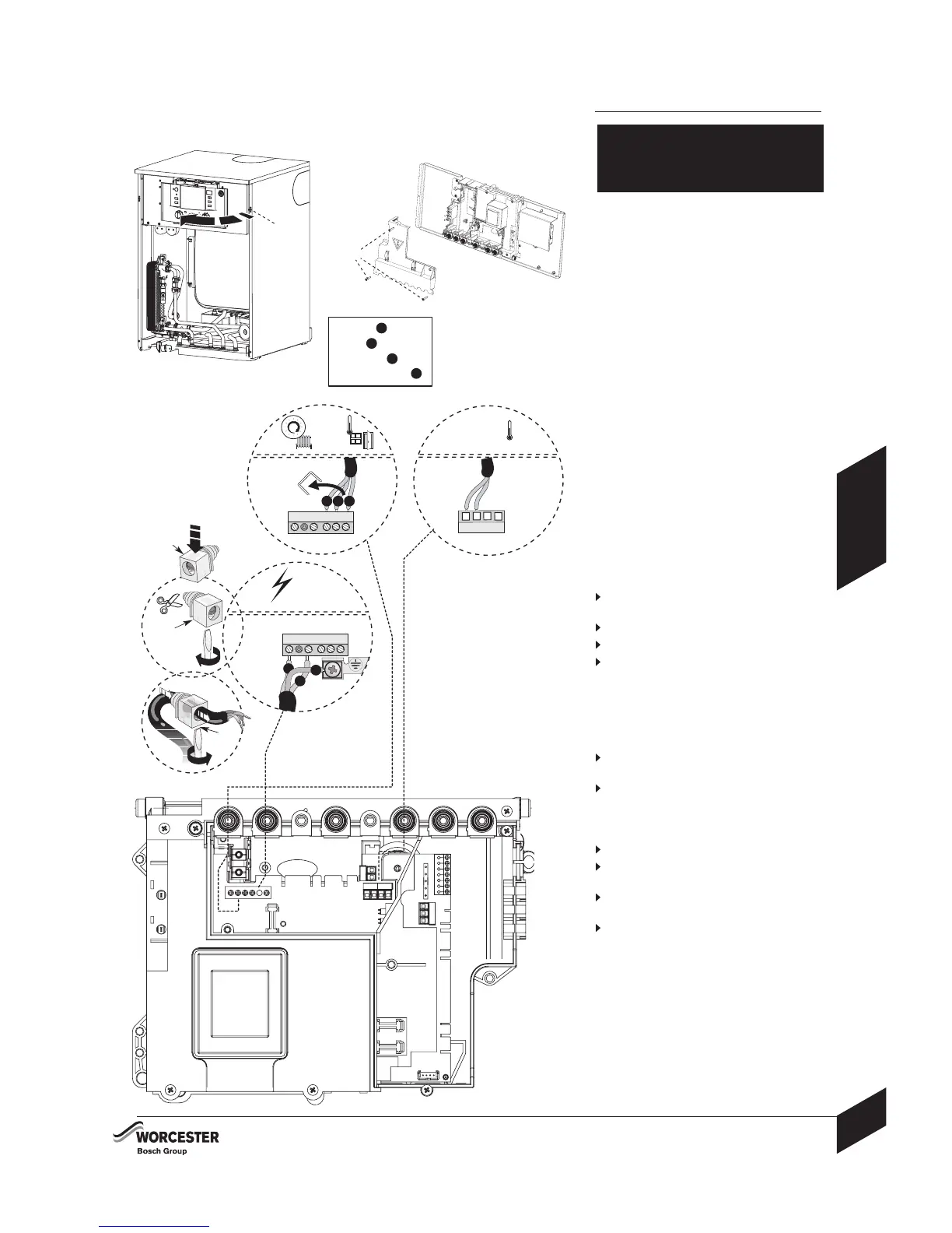
When stripping wires ensure copper strands
do not fall into the control box.
Access to electrical connections:
Remove boiler casing to access control panel.
1 Remove screw (A) and swing the control
panel into the service position.
2 Remove the three screws (B) in the control
panel and remove the connections cover.
3 Unclip cable clamp (C).
4 Cut off the tapered cable entry to suit the
cable diameter.
5 Unscrew cable retaining screw (D).
Run the cable through the cable clamp (C)
ensuring there is ample cable to reach the
connectors. Tighten the cable retaining
screw D to secure the cable and replace
clamp C into the control panel.
6 Mains power 230 Volt connection ST10:
Separate wires from cable end and strip
to 6mm
Connect LIVE wire to terminal L
Connect NEUTRAL wire to terminal N
Connect EARTH wire to connector
NOTE:
Make the EARTH wire longer so that if the
cable is snagged, the EARTH wire is the last
to be pulled out.
7 Optional frost thermostat connection ST6:
Connect frost thermostat supply wire to
terminal Fs
Connect frost thermostat return wire to
terminal F
R
8 230V room thermostat and/or external timer
ST10:
Remove link
Connect room thermostat LIVE supply to
terminal Ls
Connect room thermostat LIVE return to
terminal L
R
Connect room thermostat NEUTRAL to
terminal Ns
9 Refit all panels
Refer to manufacturers instructions when
connecting external parts to the wiring centre.
Worcester, Bosch Group cannot be held
responsible for wiring errors.
ELECTRICAL
CAUTION: ISOLATE THE MAINS
ELECTRICITY SUPPLY BEFORE STARTING
ANY WORK AND OBSERVE ALL RELEVANT
SAFETY PRECAUTIONS
INSTALLATION
INSTALLATION & SERVICING INSTRUCTIONS
31
ELECTRICAL
8 716 115 219b (09.2008)
LN
L
ST10
N
E
EARTH =
E
LIVE =
L
NEUTRAL =
N
230 V
L
R
L
S
N
S
6
3
AND
/OR
LN
ST10
L
R
L
S
N
S
S
L
N
S
F
R
F
S
N
P
L
P
FROST
THERMOSTAT
ST10
ST6
SWITCHED LIVE =
S
3
4
5
6
78
6 720 614562-04.1O
C
D
D
2
1
A
B