28 Sec. Kerosene 0.50 60°ES 110 1.40 1.77 215 10.5 8.5 17 58,000 15 51,000
28 Sec. Kerosene 0.55 80°EH 100 1.59 2.01 225 10.5 8.75 19 65,000 17 58,000
28 Sec. Kerosene 0.60 60°ES 105 1.78 2.25 235 11.5 9.0 21.5 73,000 19 65,000
35 Sec. Gas Oil* 0.50 80°S 155 1.80 2.12 235 11.5 9.0 21.5 73,000 19 65,000
NOMINAL BOILER RATING AT NORMAL OPERATING TEMPERATURE
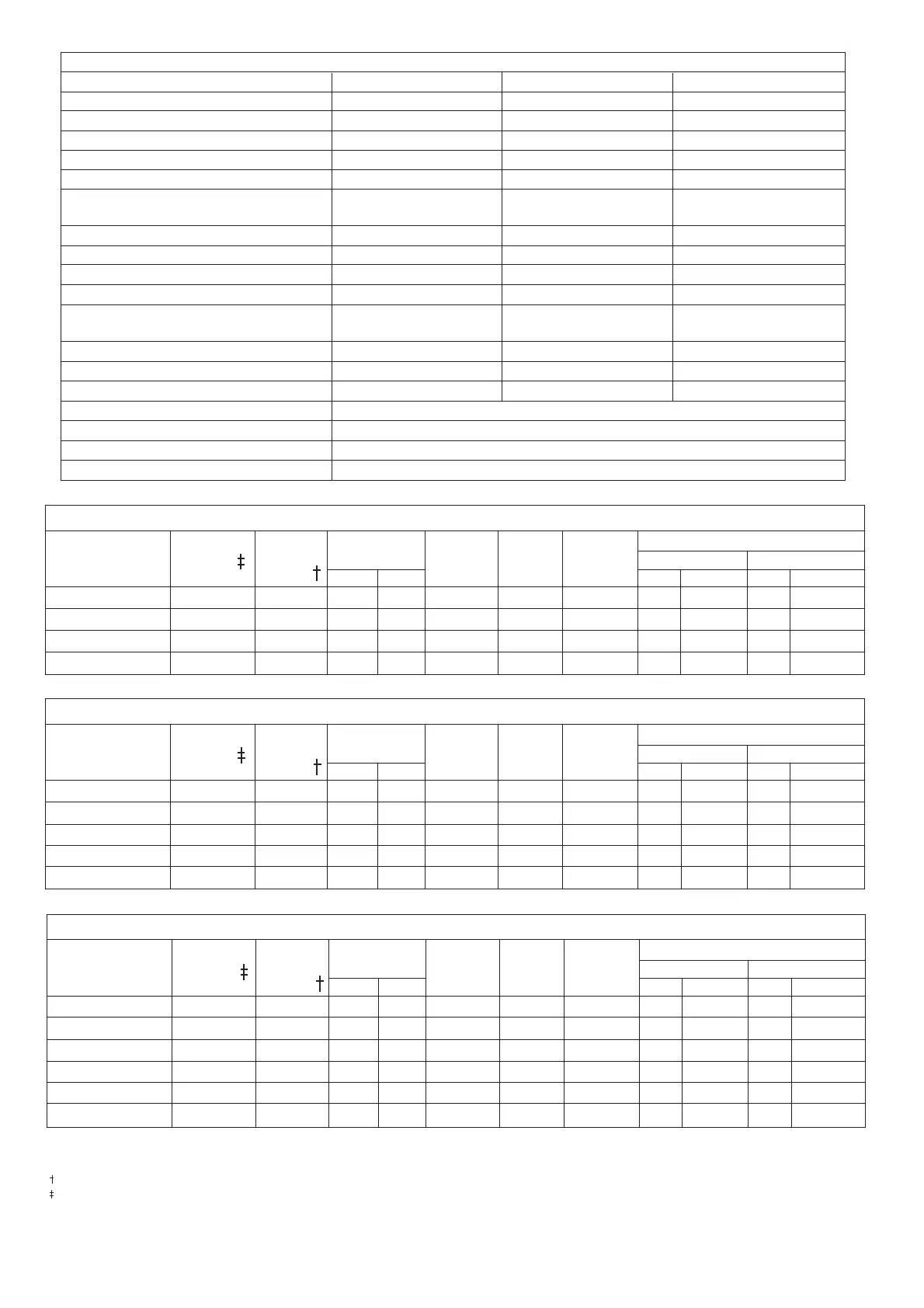
50/70 Table 2. Electro Oil Inter B9B Burner (See Fig. 13)
Fuel Nozzle
Pump
Pressure
(p.s.i.)
Fuel Flow
Rate
Flue Gas
Temp.
(°C)**
%CO
2
Approx.
Air
Setting
Appliance
Input
kW Btu/hr kW Btu/hr
Output
Kg/h l/h
3
SPECIFICATIONS
Model 50/70 70/90 90/110
POWER SUPPLY 230/240V 50 Hz 230/240V 50 Hz 230/240V 50 Hz
HEATING FLOW 1 in. BSP 1in. BSP 1
1
/
4
in. BSP
HEATING RETURN 1 in. BSP 1in. BSP 1
1
/
4
in. BSP
FUEL LINE
1
/
4
in. BSP
1
/
4
in. BSP
1
/
4
in. BSP
CONVENTIONAL FLUE DIAMETER 125 mm (5 in.) 125 mm (5 in.) 125 mm (5 in.)
MINIMUM FLUE REQUIREMENT Class 2 Class 2 Class 2
Below 260° C Below 260° C Below 260° C
HEARTH TEMPERATURE Below 100°C Below 100°C Below 100°C
MAXIMUM STATIC HEAD 30 m (98 ft.) 30 m (98 ft.) 30 m (98 ft.)
PRIMARY WATER CAPACITY 20 litres (4.4 gal.) 23.5 litres (5.2 gal.) 29.1 litres (6.4 gal.)
WEIGHT 97Kg (214 lbs.) 107 Kg (236 lbs.) 138 Kg (306 lbs.)
BURNER Electro Oil Electro Oil Electro Oil
Inter B9 B Inter B11C Sterling 40
WATER SIDE RESISTANCE 10°C Difference 8 mbar 18 mbar 35 mbar
WATER SIDE RESISTANCE 20°C Difference 6 mbar 12 mbar 19 mbar
EXIT FLUE GAS MASS FLOW 35 kg/hr 46 kg/hr 57 kg/hr
CONTROL THERMOSTAT RANGE 55°C minimum Cut In to 82°C maximum Cut Out
CONTROL THERMOSTAT DIFFERENTIAL 5°C
HIGH LIMIT THERMOSTAT SET POINT 100°C +0/-6°C
MANUAL RESET OVERHEAT THERMOSTAT 110°C +0/-6°C
Table 1
* NOTE: For use on conventional flue only.
** NOTE: The flue gas temperature is measured in the gas sampling hole on the flue outlet plate. The probe should be inserted to a depth of 50mm and angled towards the flue outlet. The temper-
ature measured is not an absolute flue gas temperature and is for general guidance purposes only!
NOTE: The pump pressure given is for general guidance only as variations in nozzle output can be up to ± 15%. It is, therefore, essential that the air is adjusted to give the correct CO
2
value.
NOTE: The nozzle type used on 28 Sec. Kerosene outputs are nozzles calibrated specifically for use with 28 Sec. Kerosene which gives less variation in nozzle output than the standard 35 Sec.
Gas Oil nozzles. However, if a 28 Sec. Kerosene nozzle is not available at servicing or commissioning it is appropriate to install a 35 Sec. Gas Oil nozzle providing the output, spray angle and
pattern of the nozzle is the same as the 28 Sec. Kerosene nozzle (e.g. 0.75 80°EH may be replaced with a 0.75 80°H).
28 Sec. Kerosene 0.60 80°EH 110 1.87 2.37 215 10.5 6.0 22.5 77,000 20 68,000
28 Sec. Kerosene 0.75 80°EH 115 2.10 2.66 225 10.5 7.0 25 86,000 22.5 77,000
28 Sec. Kerosene 0.75 80°EH 135 2.34 2.96 240 11.5 7.5 28 96,000 25 85,000
35 Sec. Gas Oil* 0.60 80°S 130 2.13 2.51 225 11.0 7.25 25 86,000 22.5 77,000
35 Sec. Gas Oil* 0.60 80°S 160 2.37 2.79 240 11.5 8.0 28 96,000 25 85,000
NOMINAL BOILER RATING AT NORMAL OPERATING TEMPERATURE
70/90 Table 3. Electro Oil Inter B11C Burner (See Fig. 14)
Fuel Nozzle
Pump
Pressure
(p.s.i.)
Fuel Flow
Rate
Flue Gas
Temp.
(°C)**
%CO
2
Approx.
Air
Setting
Appliance
Input
kW Btu/hr kW Btu/hr
Output
Kg/h l/h
28 Sec. Kerosene 0.85 80°EH 110 2.36 2.99 225 11.0-11.5 11 28.5 97,000 26 89,000
28 Sec. Kerosene 0.85 80°EH 130 2.66 3.37 240 11.0-11.5 12 32 109,000 29 99,000
28 Sec. Kerosene 1.00 80°EH 130 2.95 3.74 245 11.5-12.0 16 35.5 121,000 32 109,000
35 Sec. Gas Oil* 0.50 80°H 260 2.44 2.87 220 11.5-12.0 9 28.5 97,000 26 89,000
35 Sec. Gas Oil* 0.55 80°H 265 2.76 3.25 235 11.5-12.0 14 32 109,000 29 99,000
35 Sec. Gas Oil* 0.55 80°H 330 3.06 3.60 240 12.0-12.5 16 35.5 121,000 32 109,000
NOMINAL BOILER RATING AT NORMAL OPERATING TEMPERATURE
90/110Table 4. Electro Oil Sterling 40 Burner (See Fig. 15)
Fuel Nozzle
Pump
Pressure
(p.s.i.)
Fuel Flow
Rate
Flue Gas
Temp.
(°C)**
%CO
2
Approx.
Air
Setting
Appliance
Input
kW Btu/hr kW Btu/hr
Output
Kg/h l/h
 Loading...