Do you have a question about the Worcester Greenstar Ri and is the answer not in the manual?
Provides phone numbers for technical, service, spares, literature, training, and sales support.
Lists contact information for Fernox and Sentinel water treatment products.
Provides contact details for TFC Group for flue terminal guards.
Lists common abbreviations used in the manual, e.g., NG, LPG, CH, DHW.
Explains symbols used in diagrams for heating, water, and electrical components.
Covers appliance materials, COSHH regulations, and general safety guidelines.
Guidelines for installation by competent engineers and prohibiting unauthorized modifications.
Importance of annual servicing by qualified engineers using approved spares.
Adherence to Gas Safety, IEE, Building Regulations, and British Standards.
Requirements for LPG, timber-framed buildings, and potable water systems.
Lists all items included in the boiler's standard packaging.
Details main features like pre-wiring, digital control, and frost thermostat.
Output and pressure data for central heating modes.
Details gas consumption rates and flue gas temperatures.
Information on electrical requirements and condensate rates.
Data on SEDBUK rating, IP rating, and noise levels.
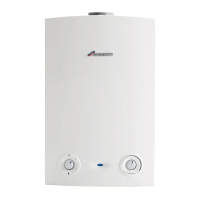
Lists and labels all internal and external parts of the boiler.
Details connections for gas, water, and condensate systems.
Ensures the system is in good working order before cleaning.
Step-by-step guide for flushing the heating system.
Specifies voltage, frequency, cable type, and earthing for the mains supply.
Details connection to meters/regulators and compliance with BS6891 for gas supply.
Guidelines for plastic pipework and underfloor heating systems.
Details standard connections, valves, and system requirements.
Specific requirements for fully pumped sealed central heating systems.
Specifies pipe material, fall, route, and insulation for condensate.
Illustrates various methods for discharging condensate safely.
Specifies clearances and access for compartments and general installation.
Details ventilation needs based on clearances in compartments.
Defines safety zones and restricts electrical controls in bathrooms.
Details 22mm compression fittings for heating and gas connections.
Table detailing minimum distances for flue terminals according to BS5440.
Guidance on flue terminal placement to avoid obstructions and nuisances.
Shows components and maximum lengths for 100mm and 125mm flue systems.
Instructions on how to calculate total flue length considering bends and extensions.
Safety advice for handling and lifting the boiler during unpacking.
Guidance on removing packaging, handling the appliance, and checking contents.
Instructions for attaching the wall plate and drilling the flue opening.
Procedures for installing rear and side flue outlets, including angles.
Detailed procedure for removing the boiler's outer casing.
Instructions for fixing the wall plate and connecting heating/gas pipes.
Guidance on lifting the boiler and fitting pipes before or after wall mounting.
How to measure and cut the standard 60/100mm diameter flue.
Instructions for measuring and cutting flue extensions and bend allowances.
Procedures for assembling flue components, fitting the terminal, and elbow.
Details on connecting the condensate pipe and adapter.
Requirements for mains supply, isolator, and wiring centre connection.
Steps for accessing the control panel and connecting wires.
Illustrates the layout and connections of internal electrical components.
Checks for pipe connections, gas type, and condensate pipe.
Instructions for isolating the boiler if commissioning is delayed.
Steps for filling the system, venting air from the boiler and radiators.
Procedure for purging the gas supply and testing for soundness.
Steps for switching the appliance on and setting controls.
How to reset the boiler if it enters flame lock-out.
Instructions for cleaning the system and adding flushing agent.
Guide for adding inhibitor and pressurising sealed systems.
Procedure to check and set the gas inlet pressure.
How to measure gas rate and working pressure.
Steps for refitting the bottom panel, outer casing, and screws.
Completing the checklist and demonstrating controls to the user.
Importance of regular servicing by qualified engineers and frequency.
Checking flue terminal, service space, and system joints for leaks.
Procedures for removing the outer case and accessing controls.
How to move the boiler control to a service-friendly position.
Information on cleaning the heat exchanger and checking fan pressure.
Procedure to set the boiler to maximum for testing.
Emphasizes competent person requirement and analyser use for combustion testing.
Steps for cleaning the heat exchanger and removing/cleaning the syphon.
Steps to remove the fan and air/gas manifold assembly.
Procedures for disconnecting electrodes and removing the burner.
Instructions for removing the burner, baffles, and cleaning the heat exchanger.
Isolating supply, removing case and cover to access control box.
Using the tool to set the mode switch to maximum for testing.
Connecting manometer and measuring CO2 at air/gas outlet adjuster.
Setting the mode switch and adjusting the gas valve for minimum output CO2.
Steps for removing the outer case and accessing primary sensor, thermostats.
Procedures for replacing the primary sensor and overheat/flue thermostats.
How to reposition the boiler control for servicing.
Procedures for replacing the gas valve and syphon.
Instructions for replacing the PCB fuse and transformer.
Steps to access and replace PCB fuse, transformer, and code plug.
Steps to remove the fan, air/gas manifold, and associated parts.
Procedure for replacing the pressure switch.
Steps to remove and replace the fan.
Procedures for replacing electrodes and the burner.
Instructions for removing and replacing the heat exchanger.
Lists part numbers and GC numbers for fan, burner, and gas valve.
Lists part numbers and GC numbers for control board, sensors, and thermostats.
Lists part numbers and GC numbers for fuses, electrodes, seals, etc.
Steps for converting 12/15kW models to LPG, including code plug.
Steps for converting 18/24kW models to LPG, including code plug and adjuster.
Details on terminal blocks, fuses, and mains supply connections.
Identifies wiring for spark transformer, pump, NTC sensor, and overheat sensors.
Initial electrical checks for earth continuity, short circuits, polarity, and resistance.
Table of fault indications (lights, flashes) and possible solutions.
Flowchart illustrating the boiler's operating sequence and logic.
Details on safety features like over-temperature and pump anti-seize.
Checklists for time/temperature controls, zone valves, and bypass.
Confirmation of system flushing and cleaner usage.
Recording gas rate, pressures, temperatures, and CO/CO2 ratios.
Confirmation of installation compliance, demonstration, and literature handover.
Template for recording service details by engineers.
| Type | Regular |
|---|---|
| Fuel Type | Natural Gas |
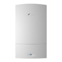
| Mounting | Wall-mounted |
| ERP Rating | A |
| Central Heating Flow Temperature Range | 30°C to 80°C |
| Standard Warranty | 5 Years |
| Dimensions | 600 x 390 x 270 mm |




 Loading...