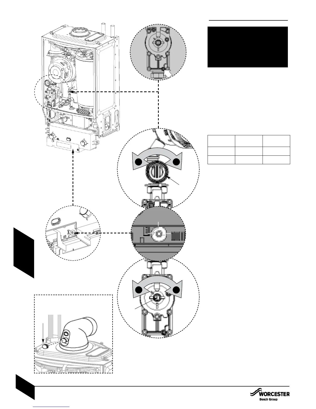
1.4 Remove covers from the air/gas outlet
adjuster and gas valve adjuster. Connect
manometer to inlet pressure point on the
gas valve.
The boiler should be run for 10 minutes before
taking a CO2 measurement and compared
with the figure in the table below.
1.5 If required, use a flat blade screwdriver to
set the CO2 (A) to the figure in the table below.
The CO must also be checked and be below
200ppm (0.002 ratio)
Measure the inlet pressure, it should be no
less than 18.5mb for natural gas and 37mb
for LPG.
1.6 Set the mode switch to minimum
1.7 Measure the CO2, it should now be at the
figure for minimum output. If not adjust (B)
on the gas valve until correct.
Return to maximum and re-check the CO2. If
correct set the mode switch to normal and
isolate mains supply.
Remove manometer and re-seal inlet pressure
point on gas valve.
Re-assemble and refit boiler case.
Re-connect mains electrical supply and
check boiler operation as stated in the
commissioning section of the Installation,
commissioning & Servicing Instructions.
1.4
1.5
1.7
1.6
Inlet Test Nipple
+
–
B
A
+
–
Gas type
CO
2 settings for Greenstar Ri
Natural gas
LPG
9.8%
+/– 0.2
11.0% +/– 0.2
9.2% +/– 0.2
10.5% +/– 0.2
CO2 setting
maximum
CO2 setting
minimum
MAX
NORM
MIN
SETTING THE GAS / AIR RATIO
INSTALLATION & SERVICING INSTRUCTIONS FOR WORCESTER BOSCH GREENSTAR Ri
8 716 109 699a (05/05)
39
SETTING THE GAS / AIR RATIO
THE SETTING OF THE GAS RATIO MUST BE
CARRIED OUT BY A COMPETENT PERSON.
SETTING OF THE GAS RATIO MUST NOT BE
ATTEMPTED UNLESS THE PERSON
CARRYING OUT THE CONVERSION IS
EQUIPPED WITH A COMBUSTION ANALYSER
CONFORMING TO BS 7927 AND IS
COMPETENT IN ITS USE.
Please note: The flue gas test point can be
accessed on the appliance flue elbow by
removing cap C
C
SERVICING
& SPARES