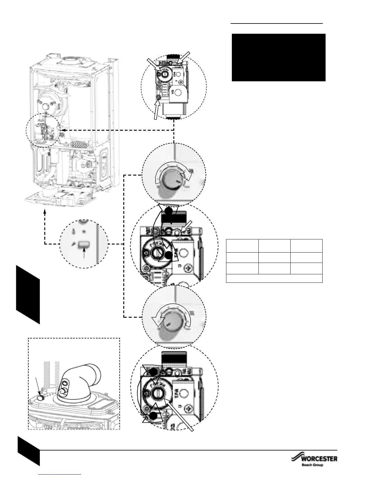
SETTING THE AIR / GAS RATIO
FOR THE SIT 848.093 SIGMA
THIS PAGE SHOWS THE SETTING PROCEDURE FOR THE SIT VALVE
FOR ALTERNATIVE VALVE SEE PAGE 55 DUNGS.
30. Setting the CO/CO
2
Note: When running in the service mode, the
boiler will operate both the central heating &
DHW circuits. This is to allow sufficient time for
the setting procedure. It will be necessary to run
sufficient water through the DHW circuit to
ensure that the boiler will not cycle on low
heating demands.
30.1 Connect manometer to inlet pressure point
on the gas valve.
To adjust the CO/CO
2
it will be necessary to
first operate the boiler at maximum output.
Press and hold down the service button (A) for
10 seconds until illuminated. The blue power
indicator will flash.
30.2 Turn central heating control to maximum;
the boiler will then go to maximum output.
NOTE: The control will resume normal operation
after 15 minutes or if the service button is pressed
for over a second.
30.3 Using a 2.5mm allen key set the CO/CO
2
via adjuster (B) using the table below.
Check CO is less than 200ppm.
Measure the inlet pressure; it should be no
less than 18.5mb NG or 37mb for LPG.
30.4 Set the central heating control to minimum.
The boiler will go to minimum power.
30.5 Measure the CO/CO
2
and check against the
table above. If required adjust (C) on the gas
valve until the correct measurement is set.
Remove brass dust cap with flat bladed
screw driver. Then using a 4mm allen key
adjust CO
2
. Replace dust cap.
Check that the CO is less than 200ppm.
Return to maximum and re-check the
CO/CO
2
. If correct press and hold down the
service button for 2 seconds; the button will
cease to be illuminated and the blue power
indicator will be permanently illuminated.
Remove manometer and re-seal inlet pressure
point on gas valve.
Re-assemble and refit boiler case.
30.1
30.3
30.5
30.4
Inlet Test Nipple
Min
‘C’
Max
‘B’
Min
‘C’
Max
‘B’
+
I
30.2
A
Please note: The flue gas test point can be
accessed on the appliance flue elbow by
removing cap D
D
+
I
Gas type
CO/CO
2
settings for Greenstar Si
NOTE. CO/CO
2
should be measured
after 10 minutes
Natural gas
LPG
9.8% ± 0.5%
11.0% ± 0.5%
9.2% ± 0.5%
10.5 % ± 0.5 %
CO
2
setting
maximum
CO
2
setting
minimum
CO - less than 200ppm (0.002 ratio)
REPLACEMENT OF PARTS
INSTALLATION & SERVICING INSTRUCTIONS FOR WORCESTER GREENSTAR 25Si/30Si
8 716 115 165a (06/2008)
54
SERVICING
& SPARES
THE SETTING OF THE GAS RATIO MUST BE
CARRIED OUT BY A COMPETENT PERSON.
SETTING OF THE GAS RATIO MUST NOT BE
ATTEMPTED UNLESS THE PERSON
CARRYING OUT THE CONVERSION IS
EQUIPPED WITH A COMBUSTION ANALYSER
CONFORMING TO BS 7927 AND IS
COMPETENT IN ITS USE.
 Loading...