SERVICING
& SPARES
INSTALLATION & SERVICING INSTRUCTIONS
42
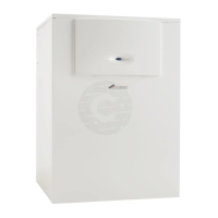
SETTING THE GAS/AIR RATIO
6-720-611-730b (12.05)
SETTING THE GAS/AIR RATIO
5 Measure the CO
2
level.
Prise off the seal on the gas flow restrictor.
Adjust the gas flow restrictor (F) to obtain the
CO
2
level given in the table above.
Measure the CO level.
If the CO level is over 200ppm, the gas
volumetric flow rate is too high. Reduce the gas
flow rate on the adjustable gas flow restrictor
until the CO level is below 100ppm.
Re-adjust the CO
2
level if necessary.
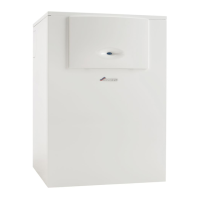
6
Turn the temperature control (E) anti-clockwise
until the display (C) shows 1 (= min. rated heat
output).
The display and the button (B) will flash.
Measure the CO2 level.
7 Remove the seal from the gas valve adjusting
screw (G) and adjust the CO
2 level to the figure
given in the table above for min. rated heat
output.
Measure the CO level.
If the CO level is over 200ppm, the gas
volumetric flow rate is too high. Reduce the gas
flow rate on the gas flow restrictor (F) until the
CO level is below 100ppm.
Re-adjust the CO
2
level if necessary.
Re-check the levels at min. and max. rated
heat output and re-adjust if necessary.
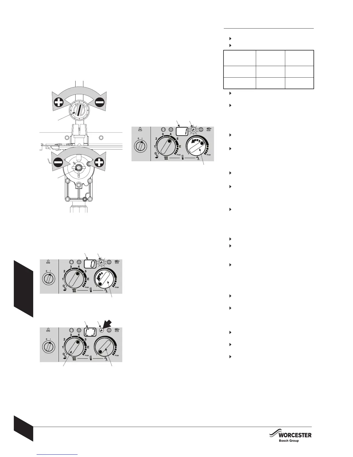
8
Turn the temperature control (E) anti-clockwise
as far as the stop so the display shows 0 (=
Normal operating mode).
The display (C) and the button (B) will flash.
9
Press and hold the button (B) until the display
(C) shows [ ].
Reset the temperature controls (D) and (E) to
their original positions.
The display (C) will revert to the CH flow
temperature.
Remove testing probe from the flue gas testing
point and refit sealing plug.
Re-seal gas valve adjusting screw and gas
flow restrictor.
Replace outer case and secure.
CB
9
7
C
8
B
E
5
F
GAS TYPE
CO
2
reading
at max. rated
heat output.
CO
2
reading
at min. rated
heat output.
Natural Gas
Type H (G20)
LPG (propane)
(G31)
9.2 ±0.2% 8.8 ±0.2%
10.8 ±0.2% 10.5 ±0.2%
G
C
B
E
6
ED
 Loading...