SERVICING
& SPARES
INSTALLATION & SERVICING INSTRUCTIONS
43
6-720-611-730b (12.05)
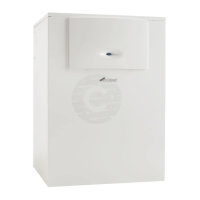
SHORT PARTS LIST
SHORT PARTS LIST
1 Burner:
Part No. 8 718 006 658 0 (GC No. E27 200)
2 Fan assembly:
Part No. 8 717 204 373 0 (GC No. E74 539)
3 Circulating Pump:
Part No. 8 717 204 443 0 (GC No. H21 229)
4 3-Way diverter valve:
Part No. 8 717 204 444 0 (GC No. H21 230)
5 Diverter valve motor:
Part No. 8 717 204 345 0 (GC No. E74 587)
6 Flow sensor:
Part No. 8 717 002 132 0 (GC No. H21 232)
7 Flow regulator:
Part No. 8 717 002 135 0 (GC No. H21 235)
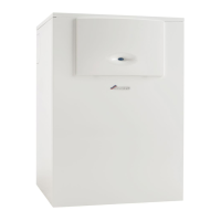
8 Temperature sensor:
Part No. 8 714 500 087 0 (GC No. E74 536)
9 Temperature limit (Flue or heat exchanger):
Part No. 8 722 963 858 0 (GC No. H08 291)
10 Thermistor sensor (Tank):
Part No. 8 716 142 319 0 (GC No. 379 785)
11 Overheat thermostat (Tank):
Part No. 8 716 103 217 0 (GC No. E82 394)
12 DHW thermister:
Part No. 8 716 142 302 0 (GC No. 375 696)
13 Heat exchanger:
Part No. 8 715 406 975 0 (GC No. H21 236)
14 Gas valve:
Part No. 8 747 003 773 0 (GC No. H08 337)
15 Condensing Pump:
Part No. 8 717 204 445 (GC No. H21 238)
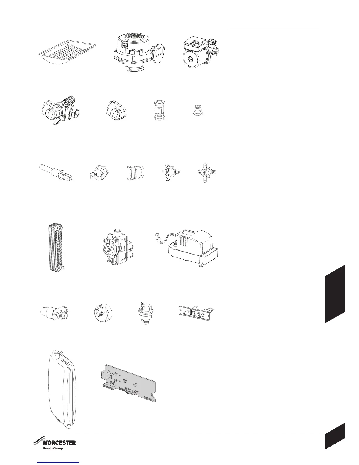
16 Pressure relief valve:
Part No. 8 716 142 416 0 (GC No. 386 789)
17 Pressure gauge:
Part No. 8 716 142 358 0 (GC No. 371 376)
18 Auto air vent:
Part No. 8 716 140 500 0 (GC No. E00 717)
19 Electrodes:
Part No. 8 718 107 078 0 (GC No. E74 535)
20 Expansion vessel:
Part No. 8 715 407 288 0 (GC No. H21 242)
21 Printed circuit board:
Part No. 8 748 300 507 0 (GC No. H21 240)
8 9 10 11 12
4567
123
13 14 15
16 17 18 19
20 21
 Loading...