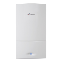
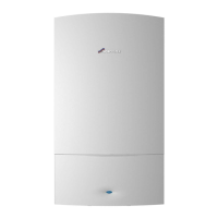
Appliance information
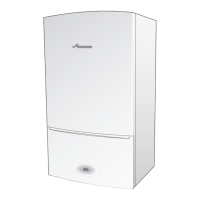
Greenstar i System
ErP
- 6 720 806 945 (2015/07)
13
Appliance features
• Aluminium-silicon heat exchanger, which has an extra-large surface area for enhanced heat exchanger efficiency.
• Low NOx emissions
• Fixed gas valve settings
• Direct burner ignition
• Zero pressure governor gas valve with fully modulating fan
• Display for appliance status and access to diagnostics, system and commissioning parameters
• Digital control system
• Memory retention after power interruption
• Low electrical power consumption during operation and stand-by modes
• Modulating pump
• Condensing in CH and DHW modes
• Eco mode, to use gas on demand
• Ability to pre-plumb condensate drain, CH flow, Gas, PRV and CH Return connections
•Large capacity siphonic condensate trap
• Galvanised steel wall mounting frame
• Standard wall frame provides vertical pipe route behind the appliance
• Compatible with all Worcester standard and intelligent controls
• Condensfit II flue systems 60/100 and 80/125 mm allows plume re-direction as standard and ability to attach plume management kits
• Front accessible components for service.
1 Main superstructure 23 DHW settings increase button/Increase button (menu edit mode)*
2 Hanging bracket 24 DHW settings decrease button/Decrease button (menu edit
mode)*
3 Removable panel - for servicing 25 CH settings decrease button
4 Ignition transformer 26 Front panel
5 Wall mounting frame 27 Control panel flap
6 Pressure relief valve connector 28 Operation/fault indicator light (blue)
7 CH return isolating valve 29 Control panel
8 Gas isolating valve 30 Appliance identification label
9 CH flow isolating valve 31 Pressure gauge
10 Condensate drain locator 32 Drain point
11 Electrode assembly 33 Blank for optional programmer
12 Overheat thermostat 34 Circulating pump
13 Heat exchanger 35 Diverter valve actuator blank
14 Fan 36 Condensate siphon
15 Fan pressure test point 37 Pressure gauge connection point
16 Gas valve 38 Automatic air vent
17 Pressure relief valve 39 Flue overheat thermostat
18 CH settings increase button 40 Combustion air inlet
19 ECO/OK button 41 Flow temperature sensor (NTC)
20 Info/Return/menu button 42 Expansion vessel
21 Appliance display 43 Bottom panel (location for optional filling link key)
22 Reset/Service engineer button 44 Expansion vessel supports (upper and lower combustion
chamber)
Table 8 Key to appliance components
 Loading...
