Service and spares
Greenstar i System
ErP
- 6 720 806 945 (2015/07)58
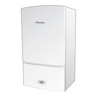
7.7.9 Exhaust assembly removal
Refer to figures 78 and 79.
▶ Remove the three screws securing the flue turret to the top of the
appliance.
▶ Rotate the upper exhaust support ring [3] anti-clockwise to
disengage from the superstructure.
The retaining sections [1] slide off the lugs [2], this allows for the
upper exhaust assembly to be remove freely.
Fig. 78 Upper exhaust assembly disconnection
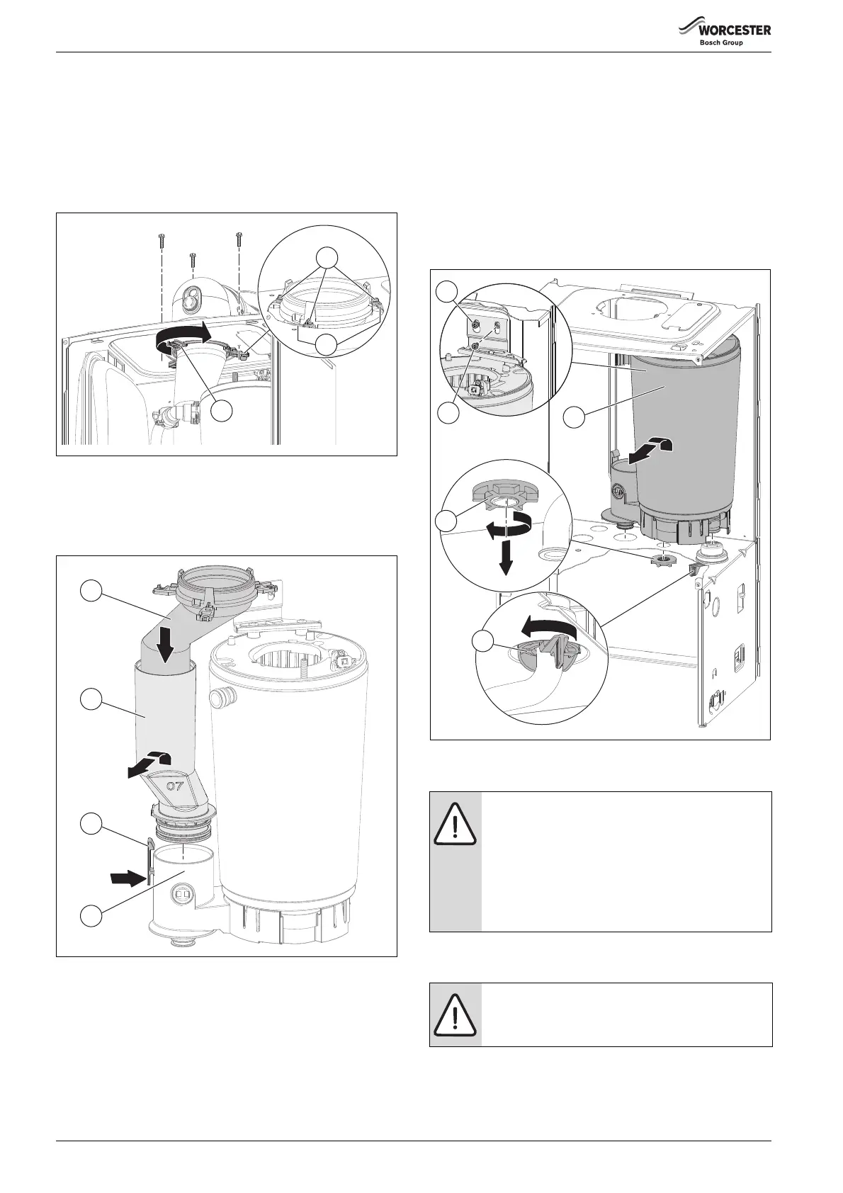
▶ Slide the upper exhaust assembly [4] into the lower exhaust
assembly enough to clear the flue exit point in the superstructure.
▶ Press the retaining clip [6] to release and lift the exhaust assembly’s
[4 and 5] from the sump assembly [7].
Fig. 79 Upper and lower exhaust assembly removal
7.7.10 Heat exchanger removal
▶ Before removing the heat exchanger, the gas valve will need to be
removed, ( section 7.7.17).
Refer to figure 80.
▶ Ensure the appliance is isolated and fully drained.
▶ Loosen the left heat exchanger retaining screw [1].
▶ Remove the right heat exchanger retaining screw [2].
▶ Unscrew the plastic sump retaining nut [3].
▶ Rotate retaining lever [4] to release the return pipe.
▶ Lift the heat exchanger and sump assembly up and out to clear
superstructure.
Fig. 80 Heat exchanger removal
7.7.11 Re-assembly of the air/gas manifold clamping plate
▶ Ensure that the new gasket is fitted, with the electrode assembly and
gasket heat shield
6720806944-41.1Wo
3
2
1
NOTICE: Heat exchanger seal
▶ If the joint between the Air/Gas manifold and heat
exchanger is disturbed the sealing gasket must be
replaced.
▶Also after re-assembly, carry out the following
checks:
Fan pressure in section 7.4,
Flue gas analysis in section 7.5.
CAUTION: Clamping plate
▶ Ensure that the clamping plate is firmly tightened
down on top of the heat exchanger.
6720806944-43.1Wo
3
5
4
1
2
 Loading...