Service and spares
Greenstar i System
ErP
- 6 720 806 945 (2015/07)
59
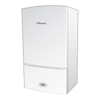
Refer to figure 81.
▶ Locate the edge of the clamping plate [2] under the bracket [1] and
fit the retaining nut [6] hand tight.
▶ Initially there will be a gap between the air/gas manifold clamping
plate [5] and the top of the heat exchanger [4].
▶ Tighten the nut [6] until the underside face of the air/gas manifold
clamping plate mates with the top of the heat exchanger [4] as
indicated by the two arrows in figure 81.
▶ It is important to clamp the plate down firmly, without over
tightening, to the heat exchanger to ensure a gas tight seal.
Fig. 81 Air/gas manifold clamping plate fitting
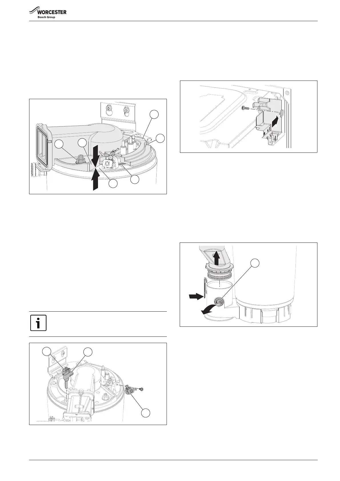
7.7.12 Primary sensor (CH NTC)
Refer to figure 82 for removal.
▶ Remove electrical connection by pulling upwards.
▶ Squeeze retaining clip [2] on plastic moulding of sensor [1] and pull
back and up until clear of pocket in heat exchanger.
▶ Pull forward to remove completely.
▶ Coat new sensor with heat conductive paste and replace.
7.7.13 Overheat thermostat
Refer to figure 82 for removal.
▶ Remove electrical connectors from thermostat.
▶ Slacken and remove fixing screw and thermostat [3].
▶ When replacing ensure thermostat sits correctly on surface of the
casting with the left hand side of thermostat sitting up against the
shoulder.
Fig. 82 Primary sensor and overheat thermostat
7.7.14 Spark generator
Refer to figure 83
▶ Remove electrical connections.
▶ Remove securing screw.
▶ Slide spark generator from bracket.
▶ When replacing ensure tab locates in bracket retainer before
securing spark generator with screw.
Fig. 83 Remove spark generator
7.7.15 Flue overheat thermostat (with grommet)
To remove and replace the thermostat either:
▶ Using a small terminal screwdriver, prise the thermostat and
grommet from the plastic housing.
Take care not to damage the plastic housing.
-or-
Refer to figure 84.
▶ Release the flue connection from the sump.
▶ Push the flue tube up.
▶ Remove electrical connections.
▶ Push the flue limit thermostat [1] out from the sump.
Fig. 84 Remove flue overheat thermostat
To replace, push the thermostat and grommet gently back into the
opening until contact with the locating ridge is felt.
It is essential that the mating surface of the thermostat is
coated with heat conductive paste.
 Loading...