6 720 610 597 GB (01.07)
6
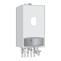
Details of the appliance
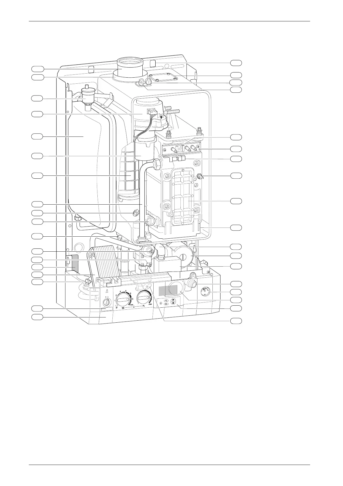
1.6 Layout of appliance
Fig. 2
4
Heatronic control
6
Heat exchanger safety temperature limiter
6.1
Hot water NTC sensor
7
Testing point for gas supply pressure
8.1
Pressure gauge
9
Flue gas temperature limiter
15
Relief valve
18
Pump
20
Expansion vessel
27
Automatic air vent
29
Air gas Mixer unit
32.1
Electrode assembly
36
Temperature sensor in CH flow
43
CH flow
63
Adjustable gas flow restrictor
64
Adjusting screw for min. gas flow volume
88
3-way valve (combi)
98
DHW flow switch (combi)
102
Inspection window
120
Fixing points
221.1
Flue duct
221.2
Combustion air intake
226
Fan assembly
295
Appliance type sticker
234
Testing point for combustion products
234.1
Testing point for combustion air
271
Flue duct
349
Cover plate for twin flue duct connection
355
Plate-type domestic hot water heat exchanger
358
Condensate trap
396 Hose Condensate trap
400 Textdisplay
415 Cover plate for cleaning access
416 Condensate collector
418 Data plate
423 Siphon
29
98
102
226
234.1
271
416
221.1
221.2
20
43
9
63
358
64
7
355
6.1
4
415
6
36
32.1
234
349
295
8.1
18
27
88
15
120
418
400
396
423
6 720 610 597 - 02.1O
 Loading...